

John Rickett 102
-
Posts
255 -
Joined
-
Last visited
-
Days Won
10
Recent Profile Visitors
1,431 profile views


John Rickett 102's Achievements
349
Reputation
-
What covering to use depends largely on what type of finish you want and how you intend to fly the model. Unless you’ve substituted the balsa wing dihedral braces for ply ones on the Southerner Major, then a (doped) fabric will offer increased strength especially if you cover the underside of the wing in one piece…to help prevent the wing folding if engaging in exuberant aerobatics! The original Southerner was intended for gentle free-flight not high G turns and loops which a radio controlled version equipped with a relatively powerful engine, such as a Laser 75, could perform. Uncovered, its quite a flimsy wing so I’d suggest using a covering which adds stiffness. I’ve been carrying out some experiments using China Silk, it’s a cheap polyester which will heat-shrink and comes in many standard colours, so if you are happy with stock colours and want to save on the time, expense and weight of a painted finish, you may consider this type of fabric, though it still needs a method of adhering the fabric and then doping. The picture below is a test piece with added simulated rib stitching to see what it looked like. Leaving aside the rib stitching the covering seems as tough as Solartex or Koverall (both now out of production) so would be a viable material if you are happy with basic colours. This test piece is 9" square, covered and doped both sides, and weighs 1oz. I built an electric powered Southerner Major and finished it in high gloss 2K car paint – completely over the top but it was an experiment in spraying this type of paint in preparation for a Shoestring under construction at the time. I was pleased with the result but it added weight which of course a coloured fabric wouldn’t. I consequently had to add lead to the nose. I also equipped it with glassed spats (with brass fittings) and a tailwheel which also contributed to the weight. Ready to go but without battery the model weighs 7lbs. The wing can carry the weight but its faster than I would like for a vintage model. The choice you have is what type of finish you want and how you intend to fly the model. I'd presume that with fitting a Laser 75 you want a spirited performance, which will be best served with a fabric covering. It would probably stooge around on a Saito 40, in which case choose a film covering.
-

Laser engines - the state of play following their closure
John Rickett 102 replied to Ron Gray's topic in IC Engines
I checked this morning that my inline 200 had been received. Geoff confirmed that they have it and that Jon should do the work on Friday....so far so good. -
Laser engines - the state of play following their closure
John Rickett 102 replied to Ron Gray's topic in IC Engines
Ok Steve, Thanks, I've now spoken to Geoff and he's confirmed that the engine should be returned straightaway and he will carry out the modification. -
Laser engines - the state of play following their closure
John Rickett 102 replied to Ron Gray's topic in IC Engines
Does anyone have news on how the inlines are going to be rectified. On June 8th Jon Harper said he had been given the go-ahead, however a recent post on the Laser Engines Owners Group, said the following: Picked up the inline twins from Geoff the other day, he’s very busy trying wrap up the company and getting the last of the engines for repair done, so any problems chaps just give him a call. Seeing as there was no reply to a written letter to AGC asking how the rework would be done, I'm in a quandary as to waiting to be contacted or risk annoying someone who can help by being labelled an irritation. -
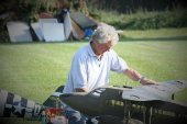
Two nylon bolts have been fine, the model was never intended to be subjected to high g forces. My theory is that if the wing is held too rigidly there's a chance of greater damage should a wing tip get caught on landing. If you make the wing seat follow the curve of the underside of the wing it should fit snugly. For the front bolt, the front former was beefed up with ply. A small platform containing the captive nut was added to move the bolt position forward. .....and zoomed in
-
That's nice John, well done. Richard, I've dug out the old Ben Buckle plan which recommends 10 degrees dihedral if the wings are built straight, which looks to be as John's above. To my mind its such a pretty design and mine does fly ok but only in gentle winds as, if a wing drops, there's quite a wallow when picking it up again. I've often thought that another ought to be built, only next time with the extra dihedral or polyhedral as originally intended.
-
Richard, Its interesting that you intend to build the Southerner Major without the tip dihedral, I did that but wished now I had increased the dihedral to compensate. My model flies ok but is quite slow to respond in roll so I only fly it in calm conditions. I'm sure it would have been better with a greater angle. It won't look as pretty (though that's in the eye of the beholder) but will probably be more responsive. The plan states that the dihedral should be increased if the wing isn't polyhedral, but I knew better.....
-
The SE5 is up for sale on the BMFA Classifieds website. https://classifieds.bmfa.org/acadp_listings/db-sport-scale-se5 I've had a few enquiries but it seems Lincolnshire is too far away for those interested.The asking price is now £350. I'm prepared to let the engine go with the model but don't know what a later style 200v is worth, so offers are invited!
-
Robert, I've used the stationery file springs method for years and all the makes seem to fit OS plugs just right. If they are a too big for your plugs they can be flattened a bit in a vice. The modern curtain wire springs (all from China?) have a smaller diameter that those of old and cannot be forced open enough - if you find a source that will fit OS plugs please let us know. You could also try these springs though a bit more expensive than stationery files, but they should still produce quite a few connectors.
-
As rusting seems to be more prevalent with glow than petrol engines, would it be better to forego the benefits of nitro in fuels and use straight methanol/oil instead?
-
The flexy springs used in spiral stationery files make good connectors. Perhaps not as easy to come by nowadays but a search of stationery suppliers should reveal something.
-
On any other Laser, (and this is just 2 x 100s) the sealant is silicone so won't offer much in the way of an adhesive. The housing should just pull away, they are only a push fit.
-
-
Having installed the motor and run it, some spitting back when nearly at full throttle was evident from the right hand carb. I suspected a broken valve spring (rare but not completely unknown) as I’ve seen before that a Laser can continue to run with a broken spring, but with the rocker cover removed all looked good. Back in the workroom and with the head off, some paraffin was poured into both intakes to check for leakage. Sure enough it wasn’t long before the paraffin appeared in the cylinder head and the level had dropped in the carb intake, so - exhaust valve good, inlet valve not. I thought it would be a fairly simple job to remove the valve, check the faces and lap the seats. Not wanting to run the risk of losing a collet, I tried working with the cylinder head and hands in a large plastic bag, but the bag fogged too quickly and I couldn’t (with my aging thumbs) push against the springs far enough to release the collets. And all the time I was worried that if I lost a collet, it would effectively be the end of the motor until (if) collets are included in the spares that have been slated to be available. I have a later version of the 200v which was planned to be used in the SE5 if the original couldn’t be repaired, though I wasn’t expecting a problem with a passing valve – time to swap motors. Apart from the external cosmetic differences, the dimensions are the same. The backplate also has the same spacing and hole size as the earlier engine so it’s a simple swap. The original engine can go into a cupboard until such time as the situation with Laser spares is clearer or I can improvise a valve compressor. The repair efforts came to fruition with having two flights last weekend, the weather was gloomy and perhaps a bit gusty for this type of model but nevertheless successful, so it was a satisfying end to the repairs. Before I put the model up for sale elsewhere, does any RCM&E forumite want a DB SE5?......Proven flyer, covered in cloth and painted with 2K fuel proof paint, Mick Reeves silver soldered rigging, Futaba servos, closed loop control on rudder, both elevator halves and tail skid. The engine mounting is for a Laser V twin, if another engine was to be fitted the (plywood) mount would have to be released from the bulkhead, or simply cut off. The bulkhead sits 138mm back from the front of the model, the engine mount itself is 105mm from the front. The 200v is available if the complete model is wanted.
-
Laser engines - the state of play following their closure
John Rickett 102 replied to Ron Gray's topic in IC Engines
I've heard nothing Ron. Unfortunately but perhaps unsurprisingly, the letter went unanswered.
