Richard Ashworth Posted September 8, 2018 Share Posted September 8, 2018 Four foamies and two ARTFs after having retirement and started in rc power (electric) flying I got the building bug. Firstly thanks to everyone who posts on this site for some cracking reads and especially High Wycombe and District Model Aircraft Club for their Feb 2018 mass Hornet build blog. Kit bought May 2018, quick delivery, box a bit dished but contents ok, and started looking at the plans and the "glue it together" instructions then pondering and planning. Mid July lots of "bits and tools" that might be needed and ready to go, wife's car banished from construction hangar (garage) for the summer. First task as HWDMAC extend right side of fuz to match left, but also deepen the underneath of the nose to give cooling access and space for ESC under the battery in the hatch area. Size of 4s 3300 battery checked for layout and servo placements. Going to be "tight" but ok getting weight forward. Glue on ply doublers using aliphatic (aliphatic and epoxy main glues used) Made sure left and right! Former layout marked from the plan and layouts checked Quote Link to comment Share on other sites More sharing options...
Richard Ashworth Posted September 8, 2018 Author Share Posted September 8, 2018 Formers epoxied in place and sides joined. Thinking ahead, balsa side rails put on both sides for battery tray, elevator & rudder servo tray and a series of 1cm square balsa tabs drilled as snake supports full length. Lots of measuring for positions based on the sizes. Servo tray and snakes glued in. Quote Link to comment Share on other sites More sharing options...
Richard Ashworth Posted September 8, 2018 Author Share Posted September 8, 2018 Rear turtle glued on with aliphatic, T pins and masking tape. It was actually a fairly good fit. Cunning plan 1. A 9mm ply firewall was made, drilled for Tnuts, ventilation and ESC - Motor wires and epoxied in, I was not happy with the kits firewall strength as it was to take the I/c motor mount, part cut away for the front u/c leg. A second false firewall was also made, channelled for the u/c leg that would sit held against the firewall so that from the front it would be motor, X mount, stand offs, false firewall, firewall all bolted through by 4 3M 50mm bolts. Out of order but Edited By Richard Ashworth on 08/09/2018 12:10:47 Quote Link to comment Share on other sites More sharing options...
Richard Ashworth Posted September 8, 2018 Author Share Posted September 8, 2018 The first of the jobs I was NOT looking forward to was making the wings as I had not previously even seen foam veneered wings but if it was going to fly it would need them so:- Torque box extensions epoxied on and cutouts in the wing squared off to a fairly tight fit. Foam dug out. Put on one side and leading and trailing edges glued on, aliphatic, and shaped. Quote Link to comment Share on other sites More sharing options...
Richard Ashworth Posted September 8, 2018 Author Share Posted September 8, 2018 The middle of the ailerons wes marked and David's plane and permagrit block put to good use. Much easier than anticipated. Wing halves joined with lashings of aliphatic (bandage to follow) simple as top surface flat, no dihederal to sort. The wing match was not "perfect" but only 0.5 mm out, leading edge and false trailing edge were a fairly good match. No pictures of operation, bandage on the top of the wing cut to a mm or so less than the inside fusalage width, under wing full width bandage used. One side of the wind had its surface the size of the bandage, coated in a layer of aliphatic, the bandage laid on from the leading edge to the back using an old credit card as a squeegee to press the bandage into the glue so that it squeezed through and smoothing it on top of the bandage. Checked that the whole of the bandage was well soaked and extra glue added if unsure. After being left to dry for 24hrs the glue had dried back to leave slight dimples over the bandage surface so more coats of glue were applied as necessary leaving it to dry after each application, until the whole of the bandage had a hard smooth surface. It all took time but the wing seems very solid. Later picture with drilled wing dowels and aileron gear installed. Tailplane next. The tailplane is made up of a main surface with a small, about 8mm tapering to nothing, piece on the centre of the leading edge. Laser cutting and a taper to 0 doesn't work, so the extension was glued on then a 30mm section at each side where the piece was burned was cut out and two pieces laid in and sanded to shape. Edited By Richard Ashworth on 08/09/2018 14:20:00 Edited By Richard Ashworth on 08/09/2018 14:23:00 Edited By Richard Ashworth on 08/09/2018 14:24:32 Quote Link to comment Share on other sites More sharing options...
Richard Ashworth Posted September 8, 2018 Author Share Posted September 8, 2018 To aid in tailplane and fin location a short cocktail stitch pin was put through the tailplane. Holes were made in the ply tailplane tray and in the fin which rather than per instructions straight epoxy onto tailplane I have added two shoulders to triple the glued surface area. The elevator halves were joined with the beech joiner and its leading edge shaped. The tailplane and elevator were covered, slots cut for the mylar hinges which were lightly roughened, inserted and glued, thin CA. The hinges were then pegged by carefully drilling from underneath, 90% of the way through the wood making sure that the mylar was pierces each time, and then after flooding with aliphatic a cocktail stick peg was pushed into each drilled hole. A black sharpie pen was later used to colour all the pegs in the black elevator. Quote Link to comment Share on other sites More sharing options...
Richard Ashworth Posted September 8, 2018 Author Share Posted September 8, 2018 The front hatch was next. The plan says add a piece of overlapping wood to the rear of the hatch and use a screw to hold down the front. Ok for an infrequently opened hatch in an I/c model but impractical for electric. Solution, cut the hatch slightly shorter, short of the firewall. Two pegs at the front of the hatch going into the CA hardened deck over the firewall and a latch at the back going into the decking in front of the cockpit. A piece of 4mm lite ply was let into the front of the cockpit decking. A part depth cutout for the brass latch made at the back of the hatch and the latch epoxied in. The position for the hole in the cockpit face was ascertained by pushing the latch against the face with all assembled . Edited By Richard Ashworth on 08/09/2018 17:09:05 Quote Link to comment Share on other sites More sharing options...
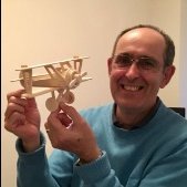
Richard Ashworth Posted September 8, 2018 Author Share Posted September 8, 2018 Jumping ahead - end product Quote Link to comment Share on other sites More sharing options...
Richard Ashworth Posted September 8, 2018 Author Share Posted September 8, 2018 And then the area I was dreading but hoped that I had a way that would work, putting the ply blocks with Tnuts in the fusalage. Firstly I cut the ply blocks to the minimum size I could that would take a full Tnut , drilled them and forced the Tnuts in by squeezing them in the bench vice. I then put a temporary spacer between them so that they were a tight fit in the fusalage. By measuring the centres I worked out where the wing dowel holes needed to be. With the wing propped on the bench with the lower surface horizontal at the dowels I put a 2mm pilot hole through the wing. Using scalpel and drills I made holes through the wing for the dowels which I drilled out 1mm oversize to give wriggle room.The dowels were then epoxied into the wing checking that bolts going through went into the receiving Tnuts. When the epoxy was set with 3/8 spacers between the dowels and ply plates and all screwed up fairly tight, protected where possible with masking tape, then epoxy on the insides of the fusalage and outside of the ply plates, everything was slid into place. Edited By Richard Ashworth on 08/09/2018 21:33:47 Quote Link to comment Share on other sites More sharing options...
Richard Ashworth Posted September 8, 2018 Author Share Posted September 8, 2018 I used 15 min epoxy so as not to be rushed and initially thought to leave the wing on overnight to fully cure but 10 minutes after putting the fitting in realised that I did not know where the epoxy may have gone so gently removed the screws and lifted the wing. Just as well, there was a small scrape of epoxy on the wing and its seating which would have been fun sorting when set! Note to self - next time CLING FILM ON WING. Sucess, the wing seats properly, the bolts go straight in, after the spacer was cut out the aileron push rods fit nicely between the ply plates. Relief! Quote Link to comment Share on other sites More sharing options...
Richard Ashworth Posted September 8, 2018 Author Share Posted September 8, 2018 And now as before, thank you to HWDMAC for the next process, "making the removable cowl". After a lot of measuring I will let the pictures tell the story. It worked! Quote Link to comment Share on other sites More sharing options...
Richard Ashworth Posted September 8, 2018 Author Share Posted September 8, 2018 A lot of covering and final fittings ESC Velcroed under battery tray (with access hatch) A little bit of fun Completed wing pre servo & pushrods Main u/c Edited By Richard Ashworth on 08/09/2018 22:34:58 Quote Link to comment Share on other sites More sharing options...
Richard Ashworth Posted September 8, 2018 Author Share Posted September 8, 2018 Nearly there. Today, 7 weeks of fun. Motor Thumper 3845 900kv 750w, Overlander 60amp ESC, Turnigy 4S 3300 30c. Maiden when weather favourable and someone with more skilled thumbs is available. If she passes, she gets her stripes. (I will add a post when I have flown her) Well, she is a Hornet (hopefully non stinging!). I hope that one day this blog may give someone the confidence and desire to build that other blogs have given me, and I apologise for its amateur nature to all the real pro builders that post and whose skills I have tried to emulate. Richard Quote Link to comment Share on other sites More sharing options...
john stones 1 - Moderator Posted September 8, 2018 Share Posted September 8, 2018 My you're a quick builder, all that in one night. Good luck with the maiden, looks right to me. Quote Link to comment Share on other sites More sharing options...
Former Member Posted September 9, 2018 Share Posted September 9, 2018 [This posting has been removed] Quote Link to comment Share on other sites More sharing options...
Piers Bowlan Posted September 9, 2018 Share Posted September 9, 2018 Very nice job Richard, thanks for sharing . Happy flying Quote Link to comment Share on other sites More sharing options...
Former Member Posted September 9, 2018 Share Posted September 9, 2018 [This posting has been removed] Quote Link to comment Share on other sites More sharing options...
Ace Posted September 9, 2018 Share Posted September 9, 2018 V nice job and appreciate you taking the time to share - must get my Scorpion twin finished. Quote Link to comment Share on other sites More sharing options...
Richard Ashworth Posted September 29, 2018 Author Share Posted September 29, 2018 Maiden done with me on the sticks! Windy day with blustery wind down the strip, took it do a motor and taxi test. Watt meter 600W 40Amps, as expected with setup. Smooth taxi to the strip and smooth right turn onto strip and 180° at the end. Much easier than expected with a fixed nose wheel and Treaded Dubro tyre. Decided to be brave and opened the taps. Smooth straight roll as per instructions and up she went. Then I found how effective the ailerons are at high power! Lots of wing rocking during a climbing turn to moderate height (elevator rudder nice, only realised afterwards that I just used them, I was only thinking ailerons!!!) One slightly ragged circuit then pulled the power to a quarter to see if I could get it down. Going slower, thumbs caught up with the plane and even with the gusty conditions it settled into one of the smoothest, most stable approaches I have ever had, easily controlled on the throttle with a moderate three pointer at the end. Enough for one day as the wind started getting stronger and more blustery. The throws were all as recommended, with 30% expo all round. I am leaving the elevator and rudder alone but for its next flights, setting aileron low rate at 60% and high at 80% of current throws and remember to use less throttle. 600w on a 4.8lb model is going to take some growing into. Quote Link to comment Share on other sites More sharing options...

Recommended Posts
Join the conversation
You can post now and register later. If you have an account, sign in now to post with your account.
Note: Your post will require moderator approval before it will be visible.