PDB Posted December 13, 2023 Share Posted December 13, 2023 (edited) One of the clubs I'm a member of suffers from poor ground conditions during the winter making the strip out of use however it has a lot of long grass areas available and it's only a few minutes from my house. On scouring Outerzone I see during the 60's small IC "rough field" models seemed popular so following building a slope soaring wing from Hobbycraft foam board I thought I would try and create a small IC belly landing model from the same material utilising 3D printed parts. I've no experience with CAD so have been learning QCAD for the 2D foam board plans and FreeCAD for the 3D parts. I've an OS15 and 25 to use, I'm going to try the 15 first and design the firewall and mount in a way that if it's not got enough grunt for a hand launch I can reprint the mount and put the 25 on the front. The model will be made from a single sheet of A1 foam board, the 2D plans are as follows and the green outer line represents the sheet of foam board. A 3d printed firewall be glued into the front end, the extra hole on the left for the throttle pushrod. Onto this the engine mount will be attached, tilting the engine over at 45 degrees. I've printed a few iterations of both in PETG and have come up with printer and slicer settings which seem strong enough. I've tile printed the 2D cad file as a PDF and will use this to cut the foam parts and build the airframe, hope to get this done in the next few days and will post updates as I go along. As you can see I have minimal experience in this area and it might not be pretty, so please feel free to chip in.😁 Edited December 14, 2023 by PDB Quote Link to comment Share on other sites More sharing options...
GrumpyGnome Posted December 14, 2023 Share Posted December 14, 2023 I'll be very (pleasantly) surprised if a 3d printed engine mount stands up to the vibration of an ic engine...... 1 Quote Link to comment Share on other sites More sharing options...
Robin Colbourne Posted December 14, 2023 Share Posted December 14, 2023 The engine bearers will be stronger if you take at least part of the lower face of the bearers all the way to the bottom of the backplate so you get more of a buttress or full length gusset effect. As you're 3D printing it you could even mould it with the engine mounting holes moulded in and counterbored hexagon holes to retain lock nuts. Some years ago I designed and a friend built a similar model to what you describe. That one was 36" span, symmetrical wing section , aileron/elevator control and used two standard size ACOMS servos and a DC Sabre 1.5cc diesel on the front. We flew it at our local sports field which for the most part was waterlogged in the winter. Great fun! 1 Quote Link to comment Share on other sites More sharing options...
PDB Posted December 27, 2023 Author Share Posted December 27, 2023 (edited) There's been a delay in completing the model because of some printing issues. I've not been totally happy with the quality of the PETG prints from my Ender 3 and after two years of getting to know it intimately I've decided I want to concentrate more on designing parts and less faffing around with the printer. I also want to use more 3D printed parts with Hobbycraft foamboard model ideas I've got so I've taken delivery of a Bambu Labs A1 (Not the combo), which will take a little time to get dialled in. I'm also changing the rear end for a v tail and have designed a printed part to make that assembly easier, I'll post up the revised design shortly once I've got rid of the Xmas relatives and can reclaim my workspace. Edited December 27, 2023 by PDB Quote Link to comment Share on other sites More sharing options...
Simon Chaddock Posted December 27, 2023 Share Posted December 27, 2023 I do have concerns at that engine mounting. A printed material is very strong and stiff along the line of the laid down filament but it many times weaker across the filaments. It would appear the whole of the engine mounts consist of filaments laid down on top of each other. This means the strength of the mount will rely entirely on how well the layer sticks to the already set previous layer. It would be possible to print the engine mount so the filament line was along the line of the bearers but to be practical it would have to be in two parts like this glued together. The glue line would be primarily in shear which glue is good at resisting. It would allow each part to be printed like this. The thickness of the part that fixes to the bulkhead would make up for the fact it is built up in layers. It would need some trials to determine the strongest proportions. Of course working in CAD there is no reason why the back of the motor mount couldn't be shaped so it IS the bulkhead. Quote Link to comment Share on other sites More sharing options...
PDB Posted December 27, 2023 Author Share Posted December 27, 2023 7 hours ago, Simon Chaddock said: I do have concerns at that engine mounting. A printed material is very strong and stiff along the line of the laid down filament but it many times weaker across the filaments. It would appear the whole of the engine mounts consist of filaments laid down on top of each other. This means the strength of the mount will rely entirely on how well the layer sticks to the already set previous layer. It would be possible to print the engine mount so the filament line was along the line of the bearers but to be practical it would have to be in two parts like this glued together. The glue line would be primarily in shear which glue is good at resisting. It would allow each part to be printed like this. The thickness of the part that fixes to the bulkhead would make up for the fact it is built up in layers. It would need some trials to determine the strongest proportions. Of course working in CAD there is no reason why the back of the motor mount couldn't be shaped so it IS the bulkhead. That's a great idea @Simon Chaddock, thank you for taking the time to explain a better alternative design, very much appreciated. As you say I can design in the bulkhead too, I'll redesign the part. Quote Link to comment Share on other sites More sharing options...
PDB Posted January 12 Author Share Posted January 12 (edited) I'm still making progress, but it's slowed as I've underestimated learning 2 and 3D CAD packages and dialling in a new printer. I kept noticing issues and tweaks I wanted to make with the 2D foamboard plans and 3D parts and to implement these has meant learning some new functions in the packages. I've used Ender 3's for a couple of years and wanted to concentrate more on designing and printing parts with less faffing around with the printer. I was looking at another higher end Ender and noticed Bambu Labs released the A1 which on paper looked a lot more hands off with the bonus of printing up to 10x's faster. I've found some pros and cons with the A1, cons are out of the box the print profiles utilise the high speeds the printer is capable of but this leads to it shaking quite violently and is extremely noisy however reducing the print speed back to a sensible level has calmed it down. A major pro is it being built to handle high speeds it has a chunky frame and base with bearings on the linear rail instead of v wheels in a channel so at more reasonable speeds it's feels very solid, smooth and stable. It also has more technology to automate bed levelling, z offset, etc. so once dialled in should be more hands off. I found my previous filament settings didn't transfer exactly to the A1 so dialling those in has also taken a lot of time but I'm getting very close now. As a long standing Cura user learning a new slicer Bambu Studio has also slowed things down, the terminology and UI differences take time to get your head around. However I've moved to the fork Orcaslicer because it has built in calibration models speeding up dialling in new filaments. Revised plan with v tail In an effort to keep weight down I'm now testing some different adhesives for foam to foam, PLA to foam and PETG to foam. Got the servos and RX sorted, just waiting for the flight pack to arrive then hope to get a model mocked up shortly. Edited January 12 by PDB 1 Quote Link to comment Share on other sites More sharing options...
Nigel R Posted January 13 Share Posted January 13 Must admit the engine mount is one bit i can't see the advantage of printing. What will it get you over one of the usual commercial nylon beam mounts? 1 Quote Link to comment Share on other sites More sharing options...
PDB Posted January 13 Author Share Posted January 13 (edited) 8 hours ago, Nigel R said: Must admit the engine mount is one bit i can't see the advantage of printing. What will it get you over one of the usual commercial nylon beam mounts? I’ve tried two off the shelf nylon mounts and both had issues with the OS15LA. The mount with a radial rear, the arms were too short due to the engines rear mounted needle valve which sticks out a long way. I tried a second mount which was two separate arms, this obscured the route to the throttle arm hence I couldn’t work out a clear route for the pushrod. I took the decision to design and print a mount specifically to address these issues and so far on the bench runs I’ve done it has been fine. The next model I’m thinking of is to use an OS25 I have and I do hope to use an off the shelf mount for it. Edited January 13 by PDB 1 Quote Link to comment Share on other sites More sharing options...
Nigel R Posted January 15 Share Posted January 15 A thought, the remote needle can be mounted literally anywhere. Perhaps a different bracket could be made from metal (recycled baked bean tin) or a printed bracket / holder / adaptor? 1 Quote Link to comment Share on other sites More sharing options...
PDB Posted January 22 Author Share Posted January 22 (edited) I've got the 3D printer dialed in OK now but hit a couple of other snags. The first was the tiled prints of the 2D CAD files were not printing at 100% scale because the HP printer driver was putting a 2.5mm border on every page despite choosing borderless and because I had squeezed the drawing into an A1 foam sheet it was reducing the size of the pages which I only discovered after cutting all the parts out, duh. This was resolved via the multi page printing function in QCAD by tile printing on a larger number of pages which negated the effects of the border. My fuselage uses what's known as a B fold in the flite test world, involves a couple of scores then the removal of the material between the scores prior to folding. However I found I couldn't remove the material between the score lines on our Hobbycraft foamboard because of how strong the adhesive is with the paper skin. To resolve this I've printed a small tool which when pushed between the score lines removes the material more neatly. Hopefully I'll have a mockup of the model shortly if I don't hit anymore snags. Edited January 22 by PDB Quote Link to comment Share on other sites More sharing options...
PDB Posted January 22 Author Share Posted January 22 On 15/01/2024 at 10:55, Nigel R said: A thought, the remote needle can be mounted literally anywhere. Perhaps a different bracket could be made from metal (recycled baked bean tin) or a printed bracket / holder / adaptor? You're crediting me with practical skills, tools and a work space............................................none of which I have. 🙂 1 Quote Link to comment Share on other sites More sharing options...
PDB Posted January 28 Author Share Posted January 28 (edited) A quick mock up of how the rear v-tail will be constructed using a lower frame and upper clamp to secure the foam flying surfaces at a 110 deg angle and true to the fuselage. Lower frame printed with a section of fuselage. Upper clamp with nylon M3 screws to hold everything together. Underneath view of upper clamp showing extruded sections to key in foam surfaces. Lower frame located in the B folded fuselage. On another Hobbycraft foamboard model I built I've had failures on anything glued to the paper surface hence trying to avoid that, this frame is glued directly to foam surfaces. Clamp on top holding the v-tail surfaces in place. The mock up showed I had some dimensions wrong and some flex which can be removed with a redesign of the upper clamp. Finding it a steep learning process with CAD but it's starting to click. Edited January 28 by PDB 1 Quote Link to comment Share on other sites More sharing options...
PDB Posted February 6 Author Share Posted February 6 All the bits ready now for assembling. I want a model that can be hand launched but I don’t know if an OS15 will be powerful enough as everything so far weighs approx 500 grams without covering or glue. The two heaviest items. If it’s not man enough I can reprint the mount for an OS25 I have. Quote Link to comment Share on other sites More sharing options...
PDB Posted February 11 Author Share Posted February 11 V tail coming together. 1 Quote Link to comment Share on other sites More sharing options...
PDB Posted February 20 Author Share Posted February 20 (edited) On fitting normal control horns for the v tail elevator surfaces realised they control horns stick out sideways, duh! Back to CAD and printed these which hang down correctly. Wing dowels with plates to prevent pulling through the foam. Some more covering with scraps of film done. Maiden planned for next week. Edited February 20 by PDB 1 Quote Link to comment Share on other sites More sharing options...
PDB Posted February 29 Author Share Posted February 29 (edited) V1.2 is in the making now, I made a pigs ear of dimensions ending up with tail surfaces way too big and the wing too small, I'm also taking the opportunity to redesign some of the 3D printed parts as well with which issues became apparent when assembling the first airframe. @Simon Chaddock thank you for the suggestion, the engine mount feels a lot stronger now after printing the mount in an orientation taking advantage of 3D printings grain then epoxying to two parts together.👍 Something I'll be bearing in mind as a priority when designing further parts. Nearly finished printing the revised parts despite my printer being subject to a worldwide recall and being told by the manufacturer to not use it, the quality of PETG prints are fantastic so I'll continue to use it keeping a close eye on it for any smoke. Start gluing some foamboard together tomorrow. 🙂 Edited February 29 by PDB Quote Link to comment Share on other sites More sharing options...
Simon Chaddock Posted February 29 Share Posted February 29 PDB You do realise that you could actually fly electric quite happily with that weight of battery and motor. Same power, much lighter motor and a bigger battery. Just an observation. Nice printing! I know people love servo mounts but I do wonder what the weight of that mount is when compared to that of the servo itself. 😉 Quote Link to comment Share on other sites More sharing options...
PDB Posted February 29 Author Share Posted February 29 (edited) 1 hour ago, Simon Chaddock said: PDB You do realise that you could actually fly electric quite happily with that weight of battery and motor. Same power, much lighter motor and a bigger battery. Just an observation. Nice printing! I know people love servo mounts but I do wonder what the weight of that mount is when compared to that of the servo itself. 😉 I get no enjoyment from electric I'm afraid and much prefer IC, I plan to build a larger model for a 46 I have so this small one is to get familiar with the building techniques and materials and to see if they work for me. With the last foamboard model I built it didn't take much of a control surface knock to tear the paper surface the servo was attached too so the mounts are an effort to find a more robust mounting solution for the servos. Edited February 29 by PDB Quote Link to comment Share on other sites More sharing options...
PDB Posted March 2 Author Share Posted March 2 Seems 2 steps forwards one step backwards but I'm learning loads and aiming for the same feeling of elation when my first scratch built (foamboard) model actually flew much to my surprise which keeps me going. The servos pictured in the last post were Ripmax SB09, rebadged 9 gram cheapo servos, and on bench testing them some were fluttering and two had stripped gears which gave me no confidence in using them so in the bin. I had a couple of Emax ES3352 servos earmarked for a flying wing as they're very thin so gave them a go, they feel a lot better quality and didn't play up on the workbench however as their dimensions are different back to FreeCAD to sort the servo mounts for them. I took the opportunity to make some changes to the mounts. I got a PM asking which filament I'm using, everything is being printed in eSun PETG. Just waiting for the glue to dry, then I can close the wing and move on. Quote Link to comment Share on other sites More sharing options...
PDB Posted March 11 Author Share Posted March 11 Moved onto the engine mount and firewall. After taking @Simon Chaddock advice I split the engine mount to print in two pieces making better use of the grain direction on the arms but I hit a snag with this. Due to the sharp angle at each end I was getting warping, whatever I tried including brims, rafts, different bed and material temps, etc. I couldn't completely get rid of it so had a rethink. I've print a traditional t-mount flat on the bed so I have the grain running along the arm. I tried attaching the mount to the firewall with self tappers but I was getting material fractures and wasn't confident of their strength. I tried M3 Cap Head screws which felt very secure with M3 square nuts secured in the rear of the firewall, here's a test piece. Everything draft printed and assembled felt very solid and took a lot of force to break apart, now to print the firewall with a lot more walls. Quote Link to comment Share on other sites More sharing options...
Simon Chaddock Posted March 11 Share Posted March 11 I know I am weight obsessive but does a servo need a mount? It made sense when a servo cost an arm and a leg so had to be easily reusable but now a perfectly good servo is just a fraction of the original price. Why not design a simple pad fixed to something solid and just glue it in? Non of my 36 foam planes with a total of well over 100 servos use a servo mount. If any fail they are simply cut out and replaced. It doesn't happen at all often. At the moment I only have one plane waiting for a new servo but then it is 10 years old and has been crashed more than once! Of course it is a different story if the plane weighs 5+ kg. Just an observation, It works for me, 1 Quote Link to comment Share on other sites More sharing options...
PDB Posted March 11 Author Share Posted March 11 19 minutes ago, Simon Chaddock said: I know I am weight obsessive but does a servo need a mount? It made sense when a servo cost an arm and a leg so had to be easily reusable but now a perfectly good servo is just a fraction of the original price. Why not design a simple pad fixed to something solid and just glue it in? Non of my 36 foam planes with a total of well over 100 servos use a servo mount. If any fail they are simply cut out and replaced. It doesn't happen at all often. At the moment I only have one plane waiting for a new servo but then it is 10 years old and has been crashed more than once! Of course it is a different story if the plane weighs 5+ kg. Just an observation, It works for me, It's a very valid point but a bit late to remove the mount now, this is version one which I don't expect to last for long and no doubt the overkill servo mount will be ditched for version two. 👍 Appreciate your input, thank you. 😁 1 Quote Link to comment Share on other sites More sharing options...
PDB Posted March 22 Author Share Posted March 22 Had second thoughts about this, not worth taking the risk of a PETG mount distorting or melting from the engine temperature. Now in a proper mount. On for completion next week. 1 Quote Link to comment Share on other sites More sharing options...
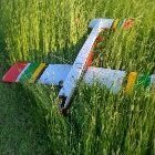
PDB Posted March 30 Author Share Posted March 30 A bit more progress, the list of jobs left for completion is getting shorter. 1 Quote Link to comment Share on other sites More sharing options...

Recommended Posts
Join the conversation
You can post now and register later. If you have an account, sign in now to post with your account.
Note: Your post will require moderator approval before it will be visible.