Steve Dunne Posted July 28, 2019 Share Posted July 28, 2019 Has anyone any good suggestions how to fix the "skewers" (don't know the correct term) that sit in the crossover between the flying wires and landing wires, to stop vibration? I used rubber bands on my old 1/5th Svenson Stampe, but would prefer something better on my upcoming Precedent. I have perused scores of photographs of full-size but can't work out how they are fixed. Steve. Quote Link to comment Share on other sites More sharing options...
Martin McIntosh Posted July 28, 2019 Share Posted July 28, 2019 Don`t understand what you mean Steve. Can you perhaps post a pic of the part? Do you mean where the opposing wires meet, if so, I did not bother on mine. Quote Link to comment Share on other sites More sharing options...
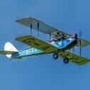
Gordon Whitehead 1 Posted July 28, 2019 Share Posted July 28, 2019 The skewers are anti-vibration rods which I assume are used to stop the wing bracing wires vibrating and rubbing against each other. Here's how I did it on my 27.5% scale Bucker Jungmeister. It's a near-scale version of what I saw on a full size Jungmeister. The stainless steel flat wires are what Flair sold for their 1/4 scale Tiger Moth. The clamps are cut from the same wire and drilled for the minute screws sold by Mick Reeves, who also sells flat wire. The rod is birch dowel. Gordon Quote Link to comment Share on other sites More sharing options...
Martin McIntosh Posted July 28, 2019 Share Posted July 28, 2019 Just got the 180 in mine as a replacement for the 155 which is now in my new Spit. Not too bad a job after sawing off the front part of the engine bulkhead so that it could be replaced with a wider piece; even the cowl fits without the baffles fouling. Will try to strip the bubbled paint from the u/c fairings and generally tidy it up whilst it is disassembled. Quote Link to comment Share on other sites More sharing options...
Steve Dunne Posted July 28, 2019 Share Posted July 28, 2019 That looks effective, Gordon. Is it based on full-size? Quote Link to comment Share on other sites More sharing options...
Gordon Whitehead 1 Posted July 28, 2019 Share Posted July 28, 2019 It is based on the full size Steve, but maybe a bit clunky. Also it just struck me that my Jungmeister's wing came off as left and right pairs along with the bracing attached. The anti-vibe rods simply stayed in place. I believe that the Stampe wings are one-piece, making this system inconvenient to assemble. On my 1/5th scale leccy Tiger Moth I used a setup copied from Dennis Bryant's .60-size Tiger Moth. Dennis' model had one-piece wings and this plug-together version might work better for you. Hope it shows on the pic as it's a screen grab of my CAD drawing. The wings on my TM come off in left and right pairs, so that on my model the rods stay locked on their wires when I remove the wings for transport. Gordon Quote Link to comment Share on other sites More sharing options...
cymaz Posted July 28, 2019 Author Share Posted July 28, 2019 A nice scale detail but the rigging wire is not functional. Love to see the result if you decide to go ahead Quote Link to comment Share on other sites More sharing options...
Gordon Whitehead 1 Posted July 28, 2019 Share Posted July 28, 2019 The rigging wires on the Precedent Stampe clearly have the function of supporting the anti-vibe rods Quote Link to comment Share on other sites More sharing options...
cymaz Posted July 28, 2019 Author Share Posted July 28, 2019 Catch 22 ! Quote Link to comment Share on other sites More sharing options...
bert baker Posted July 28, 2019 Share Posted July 28, 2019 Posted by Martin McIntosh on 28/07/2019 16:45:44: Just got the 180 in mine as a replacement for the 155 which is now in my new Spit. Not too bad a job after sawing off the front part of the engine bulkhead so that it could be replaced with a wider piece; even the cowl fits without the baffles fouling. Will try to strip the bubbled paint from the u/c fairings and generally tidy it up whilst it is disassembled. What... more power....perish the thought. Quote Link to comment Share on other sites More sharing options...
Martin McIntosh Posted July 28, 2019 Share Posted July 28, 2019 Mine was the least powerful at W&W. I seem to remember 30cc petrols being the order of the day. Need a bit more for loops, and my Spit. was overpowered. Quote Link to comment Share on other sites More sharing options...
Steve Dunne Posted August 9, 2019 Share Posted August 9, 2019 After a couple of weeks poring over the plans and manual from my new SLEC (updated Precedent) 1/4 scale Stampe kit, I think that I understand it, and have identified various areas that will need modification for the Laser 180 that is itching to get into it... I do feel, however, having seen scraps of the original plan and manual in screenshots on various forums, that the newer re-drawn SLEC plans and short manual are not as helpful as the originals. Does anyone have an old Precedent kit manual, and possibly remains of a worked-on plan, that they no longer need and might agree to sell / copy / loan to me? Many thanks Steve. Quote Link to comment Share on other sites More sharing options...
bert baker Posted August 9, 2019 Share Posted August 9, 2019 I have a original manual, Are you going to the Nationals Quote Link to comment Share on other sites More sharing options...
Jon H Posted August 9, 2019 Share Posted August 9, 2019 I have a set of worked on plans Steve but they are in reasonable condition. I will see if i can find them. I recommend a few mods straight out of the gate. Make an undercarriage that bolts on the bottom and is not built into the model like the kit version. Should you ever bend it then its going to be much easier to repair if you can take it off without having to cut the fuselage in half. change the strut mounts for the top wing to allow the bottom spar to actually connect to the centre section. As designed the bottom spar ends outboard of the cabane struts so basically the whole top wing is only supported by a single spar. The wings on my model flex like crazy and i am forever worried about pulling them off. While not that vital on my next one i intend to make the cabane struts removable as It will be much easier to cover the model without them in the way. The final thing would be that i suggest you do some sculpting of the firewall to allow better cooling. Its a flat plate as the plans and i think it could be shaped better for improved airflow. Quote Link to comment Share on other sites More sharing options...
Steve Dunne Posted August 9, 2019 Share Posted August 9, 2019 Thanks Bert and Jon! Sadly I have (yet again!) family comitments over the bank holiday, so no nats for me once again. I am happy to pay for post and packing for the manual and for the plans, please PM me if that is acceptable. Points carefully noted Jon - any more are extremely welcome at this preparation stage . Quote Link to comment Share on other sites More sharing options...
cymaz Posted August 9, 2019 Author Share Posted August 9, 2019 And, finally, the CG is incorrect on the plan Quote Link to comment Share on other sites More sharing options...
bert baker Posted August 9, 2019 Share Posted August 9, 2019 Jon I wasn’t quite sure what you meant about strut mounts for top wing bottom spar, my son is doing one atm,,he has extended wood to make strut brackets mount on strong hard points Quote Link to comment Share on other sites More sharing options...
bert baker Posted August 9, 2019 Share Posted August 9, 2019 Quote Link to comment Share on other sites More sharing options...
bert baker Posted August 9, 2019 Share Posted August 9, 2019 Or do you mean the top centre section that bolts onto the Cabaines Quote Link to comment Share on other sites More sharing options...
Jon H Posted August 9, 2019 Share Posted August 9, 2019 Posted by cymaz on 09/08/2019 13:34:53: And, finally, the CG is incorrect on the plan I balanced mine at the marks on the plans and its spot on :\ Bert, its the cabanes that are the issue as the top spar ends just outboard of them so the cabanes do not take any of the lifting loads. Its all transmitted to the lower wing through the interplane struts. I will probably extend the spar on the next one and use some sort of steel plate for strut attachment. Quote Link to comment Share on other sites More sharing options...
bert baker Posted August 9, 2019 Share Posted August 9, 2019 Quote Link to comment Share on other sites More sharing options...
cymaz Posted August 9, 2019 Author Share Posted August 9, 2019 Posted by Jon - Laser Engines on 09/08/2019 13:56:36: Posted by cymaz on 09/08/2019 13:34:53: And, finally, the CG is incorrect on the plan I balanced mine at the marks on the plans and its spot on :\ Bert, its the cabanes that are the issue as the top spar ends just outboard of them so the cabanes do not take any of the lifting loads. Its all transmitted to the lower wing through the interplane struts. I will probably extend the spar on the next one and use some sort of steel plate for strut attachment. I balanced mine and it was wayyyy tail heavy. It’s in the blog somewhere. Quote Link to comment Share on other sites More sharing options...
bert baker Posted August 9, 2019 Share Posted August 9, 2019 Ah, ok, been long morning,, will rigging sort it out yes before the hounds desend the previous owner who part built the plane decided to cover the top of the top wing first .... Quote Link to comment Share on other sites More sharing options...
bert baker Posted August 9, 2019 Share Posted August 9, 2019 I really dont understand why there's no lift support, the cabaine is fastened to the fuz,the ply plate is bollted to the cabaines, the top and bottom spars arew glued to the ply plate, perhaps with a shear web inbetween is it because the diheaderal has to be fitted at some point Mine would balance better if I had a Laser 180 Petrol,, just wiping the rain from the naughty step,, but Jon has just rebuilt my glow 180 and it does run sweet Edited By bert baker on 09/08/2019 14:14:39 Edited By bert baker on 09/08/2019 14:18:27 Quote Link to comment Share on other sites More sharing options...
Martin McIntosh Posted August 9, 2019 Share Posted August 9, 2019 The main reason that I should have thought more about the u/c and maybe cabane strut position before building is that with a fs motor there is nowhere for the original tank. Whilst people are digging out their plans I would greatly appreciate it if someone would measure the incidence between, say, the tail and the top wing. I have heard that some versions of the plan show the wrong tail incidence, and guess which one I built. My elevator has to droop by some 20deg. but does not seem to affect the flying. Nothing I can do about it now but it would just be nice to know since with each side built from 1/4sq. spruce over the plan it would be difficult to get it wrong. Looked for my plan but it must have been chucked in the loft. I expected a large cg shift with the heavier motor but it is only about 1 1/2" forward of the top wing centre TE and since the model still spins as before I shall leave it alone. Quote Link to comment Share on other sites More sharing options...

Recommended Posts
Join the conversation
You can post now and register later. If you have an account, sign in now to post with your account.
Note: Your post will require moderator approval before it will be visible.