Dwain Dibley. Posted May 20, 2017 Share Posted May 20, 2017 They have a touch of the "Nosferatu's" about them Robert....... i think it's the hands...... But they are looking the part, and will pilot the craft admirably. Well done D.D. Quote Link to comment Share on other sites More sharing options...
Robert Parker Posted May 22, 2017 Author Share Posted May 22, 2017 Thanks DD, Yes the hands are a bit iffy but once the cockpit is in place all should be fine. Hi All, The preparation is almost done and a good finish has been attained from the Poly C on it's own and with a bit of filler here and there. I have fitted the closed loop for the rudder along with fitting all of the flying surfaces with pins and then applied two coats of primer filler which I have wet and dried this evening. The Condor is back to being almost wood colour, I've now got yellow jeans, still only need this coat where it's needed. Next I'll check her over and apply any bits of filler if needed and sand back then it's on the with primer. All paints are from Halfords, the main colour will be from the Audi / VW range of course. That's all for now Regards Robert Quote Link to comment Share on other sites More sharing options...
Robert Parker Posted June 6, 2017 Author Share Posted June 6, 2017 Hi All, Just to keep you posted, I have finally got a finish to the undercoat, this took a lot longer than I thought, despite applying 7 coats of Poly C and sanding back and applying the primer filler sanding that back then applying 2 coats of grey undercoat and sanding those back then applying another coat and a light sanding and finally applying a top coat. I do regret not applying tissue as I could have saved a lot of work and elbow grease especially on the planked areas despite filling and sanding before any paint applied. There are still a few areas that I'm not too happy with the finish but overall she looks good, and last weeks good weather certainly helped with the painting. Last night I plotted out the secondary colour and will see how it looks actually wrapped around the fuselage, it's OK to draw in 2d but when set out the curves may look a little odd so I'm going to mark them out in soft pencil before committing to the design. I have also sketched out the decal positions and all seems well with the proportions so I'll drop Tim of Model Markings a line to see if he can do what I would like. No photos for a while until the painting is complete That's all for now Regards Robert Quote Link to comment Share on other sites More sharing options...
Robert Parker Posted June 11, 2017 Author Share Posted June 11, 2017 Hi All, A productive weekend with mixed results. All of the motors, esc's and the tail wheel have been soldered with 5 connections on each of the ESC's alone that is a lot of soldering and motors mounted - that's the good news. I connected the flaps and linkages and connected the rx and switched on at first all worked well then two of the four servos started working oddly, slow in operation and jittery. Now all worked before covering, the linkages are free and the hinges are not bound. I may change all four servos to a brand I trust and know. Then onto the retracts, again both worked well before covering. Today I tried them and both did then 1 stopped halfway. Having tried a few times with no movement just a buzzing noise. I removed the retract unit and plugged it directly into the rx again nothing. So I tried assisting the retract but nothing. So I stripped it down as far as it would go and all I had in my hand was the motor in my hand and tried it again. Nothing happened. I unplugged it and got out the pliers and rotated the screw thread and it moved along with the gears inside. Plugged it back in as it was and it worked. Result - no. After re-assembly plugged it back in switched on and it worked once each way then nothing. Took it apart again and it worked. The threaded pin which activates the cam is free on the thread, the cam is free in the slot . Yet when I assemble it, it only works once. Anyone else experienced this problem with E-Flight retracts. I bought them new but cannot remember who from. Regards Robert Quote Link to comment Share on other sites More sharing options...
Erfolg Posted June 11, 2017 Share Posted June 11, 2017 I have had similar issues in the past with HK units. In my case, i flipped the switch whist part way through either a retract or deployment. Since then i was advised, that what i was doing was asking for trouble. i should have completed a cycle. I replaced the unit that was causing a problem (although I purchased a pair), since then I have not had a issue. possibly for two reasons, the first is the units have not been used much, the second, I heeded the advice (which may be or maybe not valid). Quote Link to comment Share on other sites More sharing options...
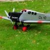
Robert Parker Posted June 15, 2017 Author Share Posted June 15, 2017 Hi All, I'm going to give you a sneak peak. I treated myself to a new camera and wanted to try it out, so with crew seated Had a little paint bleed here and there which is a little disappointing I have replaced both undercarriage units and intend to re-make the u/c legs. All motors fitted and have been test run Used a 2.4 receiver and tried flaps they are all over the place, operating at slightly different times. I tried using the flight pack instead of an rx pack but still the same. Aileron servos work great will have to tone them down a lot or she'll be snap rolls!!!! Elevator and rudder working correctly. Just have to make the three remaining cowls new u/c blocks and pins, weather it a bit and add the decals when they arrive and I think we are nearly there. Regards Robert Quote Link to comment Share on other sites More sharing options...
Dwain Dibley. Posted June 15, 2017 Share Posted June 15, 2017 I think that looks great Robert, Well Done. Out of interest, how have you got the flaps wired up, what channel etc. Assuming a Y lead, not a mix....?? could it be a sloppy servo, bad centering servo ?? D.D. Edited By Dwain Dibley. on 15/06/2017 20:22:22 Quote Link to comment Share on other sites More sharing options...
Erfolg Posted June 15, 2017 Share Posted June 15, 2017 Yes, the model does really look good. Also a change to see a civilian version, of any model where most associate the type with the military. Quote Link to comment Share on other sites More sharing options...
Robert Parker Posted June 15, 2017 Author Share Posted June 15, 2017 Thanks both, D.D, flaps wired to flap channel no mixing and they are rock solid. The really odd thing is that they all worked together before covering, sorry Poly C and paint, servos were in place during this process. All centred right, I worked on each individually checked then connected to "Y" lead. If rx turned off then back on again they still do the same thing but in a different order, they all reach max / min travel but get there eventually sometimes. The servos are Turnigy 113 MG digital, however, when the ailerons are unplugged they still behave the same. Aileron servos are Corona DS 329 MG Digital Y leads are from HK and are the under / over type connecting the inner and outer flaps while a conventional "Y" lead connects these to the RX Incidentally, when I was installing / initial setting I used a 35mhz RX, I find it easier. Then go over to 2.4 at the end of the build. I tried the 35mhz rx and they behaved the same. Perhaps I could try to do a video and upload to show, (never done this before). Erfolg, Yes, I fancied a change from my recent / future run of bombers. As I looked into the subject it drew me in, I have based mine on the 1938 record breaking non stop trans-atlantic flight from Berlin to New York. Apart from that less canopies to make. Regards Robert Quote Link to comment Share on other sites More sharing options...
Robert Parker Posted June 19, 2017 Author Share Posted June 19, 2017 Hi All, I did a bit more on Saturday and re-made the u/c leg blocks with grub screws and used cut down legs with the springs reversed to allow the legs to be retracted and they do. I'm happier with these and using the springs from the legs I hope will provide a bit of "give" on landing following my previous models although I have gained 5mm in height, the plane not me. I also did a little weathering, not too much but just enough to give that used look. Now the flap saga continues. I plugged in just the flaps to an old 35MHz receiver with a RX battery back with no other functions connected and they worked not 100% but they worked all together. Alas time ran out on me and I had to do other things, and of course yesterday was father's day where I have to do the family thing and to be honest it was a bit hot to be inside. Next with the flaps I'm going to try adding different servos to the 35MHz RX and work logically, much easier then with 2.4. I had something similar happen with the Stirling which turned out to be a dodgy servo lead. That's all for now Regards Robert Quote Link to comment Share on other sites More sharing options...
Robert Parker Posted June 24, 2017 Author Share Posted June 24, 2017 Hi All, I turned my attention to the cockpit today and here is how I got on, what do you think. Homemade canopy from the top end of one of the shampoo bottles used for the cowls, I made a balsa blank when the glue has dried I'll paint on the framing 2no 1/2" blocks and a 3/8th glued together After some sawing, shaping and sanding I had a finished result The blank was wedged into the bottle and clamped in place. I put a 3/8 sq steel bar through the neck of the bottle and then got my heat gun and warmed the whole thing gently at first then working around the blank from the back and as I got to the front pushed the bar down to pull the soft plastic around the sharp section. Allow to cool and cut out slightly larger than the blank and before you know it, it looks like this I printed off a instrument panel from the Condor from the web Although, it is difficult to see. That's all for now, next will be the cowls. Regards Robert Edited By Robert Parker on 24/06/2017 17:17:45 Quote Link to comment Share on other sites More sharing options...
Tony Bennett Posted June 24, 2017 Share Posted June 24, 2017 This is a beautiful looking model Robert. going to look fantastic in the air. Tony B Quote Link to comment Share on other sites More sharing options...
Colin Leighfield Posted June 24, 2017 Share Posted June 24, 2017 You'll be proud of this one Robert. Quote Link to comment Share on other sites More sharing options...
Robert Parker Posted June 24, 2017 Author Share Posted June 24, 2017 Thanks both, it's grown on me a lot especially now she's painted, just waiting for Tim to send me the decals and I'll post some photos. A bit different in civilian guise. Regards Robert Quote Link to comment Share on other sites More sharing options...
Robert Parker Posted June 25, 2017 Author Share Posted June 25, 2017 Hi All, I had intended to go flying but the weather was against me being a bit too wet light showers and a bit on the windy side. So I turned my attentions to the Condor which led to mixed results. I completed the cowls trimmed them off and fitted them, made the stub exhausts, the radio mast with shroud and the two "trilobite" shaped vents that fit on the top of the fuselage. Those shampoo bottles worked a treat. The exhaust stubs were made from 3/8" diameter plastic pipe These are made from balsa and the mast is hard wood. I have weighed her and she came out at 6.9lbs with a 3s 5000 lipo and 7lbs with a 3s 6000 lipo. 6 1/2lbs was my ideal weight but I'm not going to complain too much. At 7lbs she comes out at 27oz/sqft. Considering my original target weight at the start was around 10lbs, she is certainly better off for the diet, just wish I could say the same for me. Then came the shock of the build. I tried out the CoG, calculated previously from a web site which put the CoG at 117mm from the leading edge. So I set my CoG machine at 117mm and placed the Condor on the machine without a flight pack, and then I gently released my hold and the nose dropped like a stone , now I know I was very mindful of building the tail end light but not that light. I levelled her on the machine again and placed the battery pack on the fuselage on the CoG and slid it towards the tail, she balanced when the battery was halfway over the trailing edge , so I now have a redundant battery box in the nose. That is about right a good 12" aft of where I was expecting it to be. Thankfully the fuselage is very spacious and I have mounted the servos forward enough. Before going any further with the new battery box which will be a bit of a fiddle to do but not impossible and I will not have to damage / cut open any finished areas to do it, I'm going to re-check my calculations to see if I have not made any silly mistakes. That is as far as I have got and pretty much as far as I can go for now So that's all for now Regards Robert Quote Link to comment Share on other sites More sharing options...
Erfolg Posted June 25, 2017 Share Posted June 25, 2017 Robert I sympathises. I have normally sorted out the position of the battery box and other incidentals, once i have 95% finished my models. In reality not the best time, for a whole range and number of reasons. In the case of the model i am building at present, I decided to make and incorporate a battery plate as part of the build. Just as you have found, my battery box or plate needs to be at the trailing edge. Reading your post, is so very reminiscent of my own experience. I am now moving stuff around, with a view as to be in a position to get a good CG, without or by using very little extra weight. In my case the surprise is that i am building an electric model, from a IC kit, where I expected that obtaining a correct CG, would require all the gear stuffed up front as far as it would go. Quote Link to comment Share on other sites More sharing options...
Robert Parker Posted June 25, 2017 Author Share Posted June 25, 2017 Hi Erfolg, What a great build you have going there. Yes, you would expect converting a kit from IC to electric you would need to put everything as far forward as possible, and like you I don't want to add any extra weight if it can be avoided. Although, I suppose with such long nacelles plus I did make the nose cone from laminated hard balsa has not helped the cause either but it was not that heavy. Still yet to check the CoG, a task for tomorrow. Regards Robert Quote Link to comment Share on other sites More sharing options...
Robert Parker Posted June 25, 2017 Author Share Posted June 25, 2017 Hi All, I have just checked the CoG and I wish I had not. It is even further back by 7mm, not a lot I know but in the wrong direction, if I deduct the half the width of the fuselage per half span of the wing, so instead of 117mm I now have a CoG of 124mm and if I ignore the fuselage and just the pure wing it goes back by another 6mm. So the battery now goes mid fuselage. Better make sure it is well secured that is a lot of mass to shoot forwards on an arrival. I only tired the CoG with the retracts retracted. Hopefully it will not be too bad just giving a little more nose down attitude when extended. That's all for now Regards Robert Edited By Robert Parker on 25/06/2017 23:53:34 Quote Link to comment Share on other sites More sharing options...
Robert Parker Posted June 26, 2017 Author Share Posted June 26, 2017 Hi All, I have been looking at the flaps again tonight and these are my findings. 1. Connected all 4 flap servos via "Y" leads to 35Mhz RX with RX battery only - all work well. 2. Connected ailerons and gear into above RX - all channels working OK 3. Removed 35Mhz RX and replaced with spektrum 6ch DSMX RX previously bound to TX 4. Connected 4 flap servos via "Y" leads to 2.4 RX with RX battery - all work solid except 1 which jitters slightly. 5. Connected ailerons and gear into 2.4 RX with RX battery - all channels working OK RX orange lights solid. 6. Added ESC's to point 5 set up - esc's emit beeps, RX satalite orange light flashing. 7. Removed RX battery 8. Connect flight pack to point 6. - all flaps erratic in operation gear only operating on one unit, motors will run, both RX and satalite orange lights flashing. Me - puzzled. two things left to try 1. goto point 2, and add esc's to see what happens 2. try different 2.4 RX All wiring seems to be correct, the only thing I have not yet done is to add in the voltage regulator. Notes: 3 of the 4 ESC's have the middle wire disabled, ie no BEC while the 4th has BEC, This I have done on my other multi-motor set ups and they work fine. Also when plugging in the ESC's the RX receives power when the flight pack was connected. Now I hear what you are thinking, why doesn't he keep to 35Mhz, simple. 35Mhz no longer allowed to used at my club. Any ideas anyone. Regards Robert Quote Link to comment Share on other sites More sharing options...
Dwain Dibley. Posted June 26, 2017 Share Posted June 26, 2017 Hi Robert, My setup on the BF110 is as follows:- 8 channel Rx (Spektrum) Flaps in Aux 1 on a Y lead Ailerons in ail and aux 2 on a mix. 2 servos Retracts in gear on a Y lead One ESC powering Rx the other with red wire removed. Both on a Y lead to Thr channel. 1 lipo battery for each ESC I am assuming on a 6 channel Rx, aileron are on a Y lead too, as aux 2 is not available ? How many batteries are you connecting ? and which one first, it should be the one powering the esc with the red wire still connected so the Rx gets power right away. Have you tried a separate power supply for the Rx, a 5 cell Nimh for example, all red ESC wires need to be removed for this tho. Food for thought..and comparison for you. D.D. Edited By Dwain Dibley. on 26/06/2017 22:54:49 Quote Link to comment Share on other sites More sharing options...
Nik Harrison Posted June 27, 2017 Share Posted June 27, 2017 Hi Robert, Like your model. Fancied the Condor myself. Anyway the problem you describe is not too dissimilar to the problem I had on my Nijhuis A400. Using the AR8000 Rx which I had successfully used on my Beverley which used one ESC per motor I decided to use a quad controller on the A400 (cheaper). The Rx was unable to drive the 4 control signals to the quad ESC. It could drive 2, but not 4. Scope monitoring shown that the drive from the Rx was insufficient. It had worked OK in the Beverley without a problem. Solution was to build a simple transistor driver that would take the load off the Rx. This worked OK and I continued with the commissioning. Second problem was when the rudder and front wheel steering servos were connected with a Y lead. Rudder servo just went mad. Each servo worked OK if on its own. As I had already build the servo buffer I tried that. It made no difference and servos continued to go mad. Solution was to build a dual unity gain buffer for each servo. This isolated the servos from each other and they now work perfectly OK. The aileron servos are on a Y lead and no problem has been encountered with them. The elevator servos have a servo reverser on one servo and no problems with them. Electric reacts on main and front - no problem. Two servos driving the rear doors - no problem. I have tried the find if anybody else has had this problem, but no joy. All I can say is my solution works fine and so for one successful flight has been had. I did bend the front leg but I usually do anyway. Hope this helps. I have attached schematics of the circuits I used. The simple transistor driver showed that the Rx was driving less than 2mA. No idea if this is correct though. If you go down this way use the opamp drivers. Regards, Nik Quote Link to comment Share on other sites More sharing options...
Robert Parker Posted June 27, 2017 Author Share Posted June 27, 2017 Thanks both for your replies, Cracked it, all servos working including retracts, although still to connect rudder elevator and tailwheel steering. D.D, you were on the right track, I think I was heading down that route in a roundabout way of deduction and trial and terror. I removed the fourth red from the ESC so they are all in non-bec mode and introduced a 6.6v LiFe battery to the RX and a UBEC to the retracts which is powered from the flight pack and just the signal wire going to the RX. I also used the actual flight pack, 3s 6000 40C, and not a smaller flight pack from my Wellington / Catalina 3s 4000 20C. On the actual setup the orange lights on the RX are solid. Nik, Wow you certainly know your electronics, I am afraid to say that I would not know where to start, thank your for your drawings. Sounds like you had a challenging time getting your A400 sorted. Now that it is sorted I can cut down and balance the props tomorrow that arrived today, 8 x 5's reduced to 7 3/4" to prevent overlap of the inner and outer props and to prevent the fuselage being grooved. I'm using 8" instead of 7" as they are a broader prop and proved well on the Catalina and yet to find out successfully on the Wellington. That's all for now Regards Robert Quote Link to comment Share on other sites More sharing options...
Nik Harrison Posted June 27, 2017 Share Posted June 27, 2017 Hi Robert, Glad you got it all sorted. Looking forward to seeing the finished plane. Regards, Nik Quote Link to comment Share on other sites More sharing options...
Robert Parker Posted June 28, 2017 Author Share Posted June 28, 2017 Thanks Nik, Waiting for decals been a while and not heard a thing. I don't want to put up any photos until she's finished now. Regards Robert Quote Link to comment Share on other sites More sharing options...
Tony Bennett Posted June 28, 2017 Share Posted June 28, 2017 awe, go on put up a pic. she is a lovely model. Tony B Quote Link to comment Share on other sites More sharing options...

Recommended Posts
Join the conversation
You can post now and register later. If you have an account, sign in now to post with your account.
Note: Your post will require moderator approval before it will be visible.