onetenor Posted July 24, 2018 Share Posted July 24, 2018 A landing light can made from a boat searchlight. I did have two more tips but forgot what they were just now. Quote Link to comment Share on other sites More sharing options...
onetenor Posted July 25, 2018 Share Posted July 25, 2018 Here we are ! To ensure formers are the same both sides Draw half a former to a line Now fold the paper along the line and cut out the former through both pieces of paper. Unfold and you have a complete former. The shampoo in the bottles makes good spot/stain remover from mattresses and upholstery.Scrub in with a toothbrush and sponge out with a damp cloth or sponge. Mix the rest with your car shampoo or use as a shamp for the car.. Brilliant. Quote Link to comment Share on other sites More sharing options...
Robert Parker Posted August 11, 2018 Author Share Posted August 11, 2018 Hi All, New props ordered, only 1 in stock so I will have to wait until I get them, and now the weather turns. Regards Robert Quote Link to comment Share on other sites More sharing options...
Robert Parker Posted August 18, 2018 Author Share Posted August 18, 2018 Hi All, Props arrived during the week plus a new 4s 5000 battery pack. I have done some static thrust tests with my watt meter attached, below are the results 3s original 7x5 2 blade props 2lbs thrust drawing 15.8Amps and 191 watts = 27watts/lb 3s with 8x6 3 blade props 2.6lbs thrust drawing 27Amps and 315 watts = 45 watts/lb I had to trim down the new inner props to 7 3/4" to give clear the fus 4s original 7x5 2 blade props 3.2lbs thrust drawing 25Amps and 400 watts = 67 watts /lb 4s with 8x6 3 blade props 4.8lbs thurst drawing 42Amps and 695 watts = 99 watts/lb The new battery pack is 4ozs heavier than the 3s which brings the new weight up to 7lbs 4ozs. So with the new battery and prop set up the power gain is 72 watts / lb. I'm so glad she did not take off on that maiden flight. I would welcome any comments on the above results as I'm still learning this art of electric flight. Regards Robert Edited By Robert Parker on 18/08/2018 14:49:46 Edited By Robert Parker on 18/08/2018 14:51:26 Edited By Robert Parker on 18/08/2018 14:51:59 Quote Link to comment Share on other sites More sharing options...
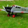
Robert Parker Posted October 8, 2018 Author Share Posted October 8, 2018 Hi All, Went flying yesterday with the intention of maidening the Condor with the new battery pack and prop combo. Pre-flight checks - done, Range check - done, Photo shoot - done. Lined up and ready to go............. .......this only took a few seconds from the previous photo and things don't look to good here. I would like to thank fellow club member and examiner Darrel for the photos So what happened to get to this point, well I gradually opened up the throttle and she started to roll straight and true opened up to get the tail up which she did then in a instant as soon as the wheels left the ground she went into a tight loop I don't think I had time to react as it all happened too quickly. I am not sure what the cause was. I re-checked the CoG after fitting the new battery. The CoG position was calculated from the net using rcplanes online cg2 using a wing with two swept wing panels. Motors, no down thurst, 2 motors on the right wing 2 degrees side thrust. props all rotating same direction. The CoG position and or the tailplane incidence are in my mind but I would welcome any thoughts Extensive damage to the fus totally gutted Appart from the wing mounts and the slit in the wing sheeting the wing seems to be salvagable Regards Robert Quote Link to comment Share on other sites More sharing options...
Martian Posted October 8, 2018 Share Posted October 8, 2018 Robert that is devastating I really feel for you Quote Link to comment Share on other sites More sharing options...
McG 6969 Posted October 8, 2018 Share Posted October 8, 2018 ... ooh, sjeesh, Robert. Don't really know what to say after all that lovely dedication you had... Hope that at least the wing will be salvaged. 'Matata' here for sure Chris Quote Link to comment Share on other sites More sharing options...
Paul C. Posted October 8, 2018 Share Posted October 8, 2018 Sad news Robert I have followed your thread from the start, although the fuselage is extensively damaged a have seen a lot worse repaired give it a day or two and take another look at it . C of G sounds as though it may be the main contributor to the crash but it also looks that the elevator still had a lot of up in the last photo or it may just be my eyes. Hope it is repairable Paul. Quote Link to comment Share on other sites More sharing options...
Erfolg Posted October 8, 2018 Share Posted October 8, 2018 It could be a CG issue. As we are constantly reminded, it is best to start with a forward CG and be safe. For an airliner, a soggy pitch response is not really an issue, if the stability is improved. It could also be an issue of longish and damp grass, slowing down the acceleration, and possibly limiting ground speed. My PT 19 was a pig to get of the ground with limited power and poor ground. When it finally could be coaxed into the air, it was often nose (high) up, with limited air speed, getting ready to re-kit itself. Re motored the issues just disappeared. I would stick it back together, forget abut the finish and try again, with a set up you think may be better. Once flying, then I would start thinking of a nice rebuild and a pretty finish. Quote Link to comment Share on other sites More sharing options...
Ken Ball 1 Posted October 9, 2018 Share Posted October 9, 2018 Sorry, don’t know what else to say. Looked really good and should fly as good. I would follow the advice from above and let it rest for a day or two, I kick rocks for a couple of days when I rekit one, Ken Ball Indiana USA Quote Link to comment Share on other sites More sharing options...
Dwain Dibley. Posted October 9, 2018 Share Posted October 9, 2018 So sorry to hear of the demise of such a beautiful model Robert, but..............it looks repairable to me. The secret is to leave it alone for a bit, to mourn, and then to get stuck in with the rebuild. The consensus seems to be C of G, and Erfolgs advice seems sound re the rebuild and test, then get the finish sorted. When I built the de'ag spit I flew it before starting the finish due to people believing it would not even get off the ground. All the best, what ever you decide to do..... D.D. Quote Link to comment Share on other sites More sharing options...
Erfolg Posted October 9, 2018 Share Posted October 9, 2018 A hand launch could be a safer bet, if you have some one in the club who has a reasonable technique. Incidents as you have experienced, have many of us thinking about similar types of personal experiences. I do not know the answers, although I can relate issues that some of my models have or continue to have. The Slingsby T67 has a long take of run, when the the grass is anything but very short. It even suffers from damp grass slowing it up. I think the issue is at least partially down to small, scalish type wheel size. The other issue i think is the model sit on the ground, the wing should be lifting being only a degree or so below the 0-0 line. When the tailplane eventually lifts the nose wheel of the ground, the model seems to be traveling quite fast. Yours being a tail dragger the same issue should not be present, although longish grass and wet ground conditions could be slowing your model up. The temptation is to inadvertently to put more up in than is desirable, together with a transitional airspeed, it can be recipe for disaster. I am guessing that you do not have an abundance of power, as many models now have, that leap of the ground having moved 100mm. My PT 19 has one other issue that has to be managed. The UC is wire that came with the kit, although now used as a std. Torsion bar set up. The wire is not stiff enough to have the resistance i would like. It can be easily induced to move about 70mm total travel at the wheel. When the grass is tufty, this movement seems to consume a lot of energy. Given the cycles per minute can be quite high it could explain where a lot of my power still disappears to. Given that Work Done = Force * distance moved through. It could relate to quite a chunk of watts. Is your UC stiff? Quote Link to comment Share on other sites More sharing options...
Robert Parker Posted October 9, 2018 Author Share Posted October 9, 2018 Thank you all for your replies and sound advice. I will certainly be kicking a few stones for a while and a re-build is to be done. As for power she had loads this time 99 watts per pound or 695 watts in total. I too had reservations about the wheels and grass being only 3", the grass was shortish and the ground conditions were fairly good. I must thank my fellow club members who earlier this year spent time digging new drainage channels which have really helped the patch as well as the moss removal. The u/c is stiff the only give is the 5mm wire pins from the units to the spreader bar for want of a better name which is only 1" long. I have not looked closely at the wreckage yet- too early. Yes there does seem to be a fair amount of "up" elevator in the last photo. The CoG is certainly a good starting point for re-calculating, not straight forward with a double swept wing, possible an error here. I'll keep you all posted on developments Once again thank you all for your support and encouragement. Regards Robert Quote Link to comment Share on other sites More sharing options...
Erfolg Posted October 9, 2018 Share Posted October 9, 2018 100 watts per pound is not bad for a civilian type model, that is once flying. It is getting the thing reliably into the air that can be an issue. My PT 19 had from memory just +100W. per lb, the take offs were marginal. Strangely, the left swing was quite pronounced, when compared to increasing the wattage by I think 50%. The swing reduced significantly and transition from running along the ground to flying is now authorative. No more struggles, and giving the (justified) impression that I am not the most skill full of fliers. I suspect that ball park estimates as to what the watts drawn is necessary, is not as valid when 4 motors, with smaller propellors, and more area of wing and nacelle to reduce efficiency. I would try a hand launch, just to get the information as to how effective the power plant is. To see if it flies like a small glider.If so, then I would be looking for more power from the motors, some how, to provide that reassurance that the power provides, at take off. Quote Link to comment Share on other sites More sharing options...
Robert Parker Posted October 9, 2018 Author Share Posted October 9, 2018 Thank you Erfolg, I may try the glider launch when the repairs are complete. Regards Robert Quote Link to comment Share on other sites More sharing options...
trevor wood 2 Posted October 10, 2018 Share Posted October 10, 2018 Robert, l agree with the recent posts that that the likely cause was a CG that was too far aft. In your early posts you describe the model having a 72" wing span, and from the inverted plan view photograph in your back garden, I estimate the wing root chord to be about 10.5". In a later post I recollect that your calculations showed the CG should be at 124mm aft of the LE. If you ignore the slight sweep back of the outer wing panels and assume a "safe" first flight CG to be at or about 25% MAC, yours should have been at about 66mm aft of the wing LE. If you want to include the affects of the slight outer panel sweep back (or are feeling particularly brave) then you might consider going to 75mm aft of LE for the next "first flight". A CG position at 124 mm would be in excess of 40% MAC, which easily accounts for the vicious pitch up you encountered. PS. I wouldn't even consider trying to persuade someone to hand launch a 7lb, 6ft span, low wing, 4 engined scale model for a first flight. Quote Link to comment Share on other sites More sharing options...
Erfolg Posted October 10, 2018 Share Posted October 10, 2018 Hmmm, the model is quite a bit heavier than I thought. I have assumed an av, chord of 9.5", which is probably optimistic, which gives a wing loading of 25 oz ft^-2. I have a few models slightly less loaded in that region. both are at 22 oz ft^-2. The difference is that they are @ 4lb and 500w at launch. The problem could well be a combination of small issues, that in themselves are trivial. The PT 19 is a case in point, where it was initially destined for the back of the hanger, due to the terrible take off regime. Add much more power and now flies every week, in some pretty awful conditions, which is typical here. This model suffered severe pitch up, when the power was low (246w), due to trying to coax it off the ground. It now is at 476W, now the speed builds very well, requiring just a small amount of up to unstick. Another 4 lb model. Another case is the PM Cassutt. It was initially flown without a UC hand launched, with the CG at the PM 25% (as per plan). I then added a UC, which required a few changes. The plan had been lost, and I forgot the CG position and it was not marked. I moved it to 30%, the best pilot in the club (he has just won the club aerobatic comp) found it a nightmare just getting on the ground, after being everywhere other than where intended. PM consulted, CG back @25% and it is a pussy cat. Now flies every week. Edited By Erfolg on 10/10/2018 12:18:09 Quote Link to comment Share on other sites More sharing options...
Piers Bowlan Posted October 10, 2018 Share Posted October 10, 2018 So sad to see a beautiful model end its maiden flight this way, commiserations Robert. Finger of blame pointing to C of G issues as a possible culprit by several posters. Just to ask the obvious, presumably the operation and reliability of the elevator servo has been comprehensively checked by now? No doubt when you were on the downside of the loop you were instinctively pulling hard on the elevator which accounts for it's position in the photo. The fuselage damage looks bad, although a repair appears quicker than a new fuselage. Good luck. Quote Link to comment Share on other sites More sharing options...
Robert Parker Posted October 10, 2018 Author Share Posted October 10, 2018 Hi All, Trevor you are very close with your estimation, it is actually 11". Those figures do make some sense. I have taken a look at my calculations and feel that I it was out. We had a club meeting tonight and it was talked about in detail and the CoG may have been a cause but also / as well the tailplane incidence could also contributed or a combination of the two or other factors waiting to be found. Erfolg, some nice models you have there, Once I make a start on looking at the debris and assess if anything could have contributed to the unscheduled arrival. Piers, I have not looked at the model since Sunday. I will check all of the servos. Although all new that does not mean perfect. If I did try to pull out of the loop it was by instinct as it all happened too quickly and was all over in a second. Regards Robert Quote Link to comment Share on other sites More sharing options...
Erfolg Posted October 11, 2018 Share Posted October 11, 2018 I guess you set the tailplane to the 0 - 0 line of the wing section? If so I think you can safely eliminate tailplane incidence. I assume that the nose section has just broken of? On that basis strapping the fuz together on a temp basis should not be to much work. I do not know about how you feel, I personally tend to see these incidents as a challenge, providing as much self satisfaction smugness, as a straight forward first flight, once the solutions are found and implemented. Quote Link to comment Share on other sites More sharing options...
J Moyler Posted October 11, 2018 Share Posted October 11, 2018 I normally just luck but I would add my support for you to get the condor flying again. Regarding comments about the amount of power available. 100 watts per pound is fine. In my limited multii-engine experience I have found that multi engine planes tend to be more powerful than expected Link . I am not sure how experienced you are with multi-engine planes but there was a post recently where someone used a ARTF Twin to gain experience before building a mosquito.Hope to see the Condor repaired and flying again. JM I think that I should of chosen a better link but it gives an idea why twins appear to be more powerful. Edited By J Moyler on 11/10/2018 10:01:11 Quote Link to comment Share on other sites More sharing options...
Erfolg Posted October 11, 2018 Share Posted October 11, 2018 I suspect that the arguments presented are misleading. Take the argument to its logical conclusion, you do not have 2 or 4 propellers to improve efficiency you arrange as many as you can along the wing. At the practical level, many multi engined full size aircraft were so because of the issues of suitable engines, as either single or twins. Many aircraft designers went from 2 engines to 4 because of engine issues, rather than as the starting point. Although some multi engines were a consequence of regulatory requirements relative to reliability issues. Without getting into the KE, area relationships etc. It is commonly accepted that a single propeller of the same area as a multiple of the same area is significantly more effecient. There are a number of reasons for why, it is not necessary to get into the sceince and maths. Althougth at a pracicle level there can be reasons as to why you may choose multiple power units. I only have two models with twin set ups, what surprises me is the weight build up from the wires ESC etc. The Delta is at 14 oz ft^-2 on with 360w. The Me 110 is @ 360W not recorded the weight, nor wing area. Quote Link to comment Share on other sites More sharing options...
Robert Parker Posted October 11, 2018 Author Share Posted October 11, 2018 Hi JM, I have some mixed experience with twins, Wellington and Catalina, and a Lancaster. The Wellington was total frustration under powered but just enough to get it of the ground and turn to up worse than the condor. The Catalina although a little difficult at first due to the ESC's timing being low once adjusted to medium she flew well take off being hit or miss actually flew quite well and the Lancaster flew like a trainer. I know where you are coming from though well we have to learn don't we sometimes the hard way. Erfolg, Yes the wiring soon puts the weight on, the wings are most of the weight. Regards Robert Quote Link to comment Share on other sites More sharing options...
Simon Chaddock Posted October 11, 2018 Share Posted October 11, 2018 My own experience with 4 engines is it is easy to under estimate the effect of the prop wash that is spread over quite a large proportion of the wing. For some aerodynamic reason when under power the CofP of the 'washed' wing area is moved significantly forward so the plane acts like it is tail heavy with an aft CofG but with the power off it becomes controllable. If the Condor has a reasonably thick wing section it will still remain longitudinally stable with a degree of down elevator applied so rather than use non scale down thrust it may be better for the throttle and elevator to be 'mixed' to achieve a consistent flight from full power to glide. Wiring weight? Pick the right plane that has really big engine nacelles then each can hold the motor, ESC and battery. Not only does such a layout structurally off load the wing but the only 'long distance' wiring is for the servos. With the rx in the wing and the elevator and rudder servo wires running in the dorsal spine the fuselage itself is completely empty! Quote Link to comment Share on other sites More sharing options...
Erfolg Posted October 12, 2018 Share Posted October 12, 2018 Simon Your models are generally very light weight, getting by with low power (although possibly having an acceptable power to weight ratio), You even go to the length of shellacked wire as the insulator. Also you normally hand launch. I find it is very easy to underestimate the power consumption absorbed by grass, where small wheels are involved, the grass is fractionally longer than usual and particularly with damp or wet grass. I ere on the side of caution with my wiring,and it has surprised me how much weight there is in the wiring from a central battery, to nacelle mounted ESC. In resent times I have considered under specifying the wiring, living with the losses during take of, as once flying the power demands reduce significantly. To be honest I do not know what the issue is with the Condor is. Although the A of A is a easy check. A forward CG reduces another risk. Since swapping from gliders to power, and starting out as a watt miser, I now know from others and my own experiences with a range of models, there is no substitute for power when taking of or launching. Gaining height is your best friend, it provides time. The other major lesson is get a really competent flier to make the first flight, watch carefully, undertake a debrief after the flight, after checking stall etc. Then correct all the issues that are revealed. Quote Link to comment Share on other sites More sharing options...

Recommended Posts
Join the conversation
You can post now and register later. If you have an account, sign in now to post with your account.
Note: Your post will require moderator approval before it will be visible.