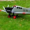
Robert Parker Posted September 9, 2017 Share Posted September 9, 2017 Hi All, I have the urge to get my drawing kit out again and I am going to have a go at the 1930's flying boat the Do 24. I could have taken the easier route of modelling the Do 18 which is built like the Catalina with respect of how the wings are connected to the fuselage. But I wanted to challenge myself. What is not to like about it. This is a hybrid using a new wing on an existing fuselage. love the photo but I'm going for the 1930's version. The original aircraft had a wingspan of 27m. So after some number crunching I'm going for a 1/16th scale model which will give it a wingspan of 66 1/2" or 1690mm and a length of 54" or 1370. Target weight 7lbs wing area 677sqin wing loading 24oz/sqin functions 5 Power TBC not sure IC or electric I purchased a 1/72nd model for guidance and reference I'm still thinking how to connect the wings to the fuselage at present but that is one of the challenges. I've got an idea how to fix the cabane struts to the fuselage but thinking on how to connect to the wing. One thought was to make the outer wing panels detachable and make the centre section of the wing as one piece with the fuselage, after looking at the figures it would take up a lot of space in that configuration. So the wings will be in one piece or have the top section of the fuselage removable and retained with wing bolts and dowel, (now that may work). If I go down the electric route then the power cables will run from the fuselage to the wing through the diagonal brace hopefully. I made a start on the outline of the fuselage today and so far it looks good with a huge fuselage at 7 1/2" wide plenty of room for the radio equipment / batteries. All set ready to go................ ......................Six hours later Tail end Nose, the camera angle has made the fuselage look thinner than it really is, I have lightly pencilled in the wing position and central motor. The diagonal line just below the cockpit is for the pontoon. That's as far as I have got so far. I intend to built the fuselage as I built the FW Condor in two halves, this has got a whole lot of curves to plank. That's all for now Regards Robert Quote Link to comment Share on other sites More sharing options...
chris meek 1 Posted September 9, 2017 Share Posted September 9, 2017 Liking your designs Robert - can you give more idea on how you go about drawing up the plans? Quite fancy trying it myself but can't think how to get the cross sections of the fuselage right... Chris Quote Link to comment Share on other sites More sharing options...
Tony Bennett Posted September 9, 2017 Share Posted September 9, 2017 Interesting project young sir. look forward to following another one of your inspiring builds. Tony B Quote Link to comment Share on other sites More sharing options...
Robert Parker Posted September 10, 2017 Author Share Posted September 10, 2017 Thanks both for your support, Tony, watching your Lancaster renovation project with interest. I've got my own 72" version to repair. Chris, well I try my best to explain how I go about drawing up my plans. My drawing equipment is quite basic and can be bought from WH Smiths, Craft stores or online and consist of a "T" square, 2 set squares (large) compass set, these I have kept since I was in technical college. I have a couple of new additions these being an A3 drawing board set and most important a digital verier caliper. Start off with a datum line or centre line, one for the cross elevation and another for the plan view. The datum line through the elevation does not have to be a centre line. This is where the plastic model comes into play. I draw around the fuselage keeping as tight as possible this gives me the outline from this I find a best fit for the datum line. I then decide where I need formers and or additional reference points any curves or other features. It is just a case of taking readings either side of the reference points and multiplying them by the scale factor, in my case this is 4.5 and transferring these figures to the drawing then it's a case of dot-to-dot. There may the odd dot that is not inline and I take a best fit. I do the same for the plan view. You can see my reference marks on the photo of the tail above. With the above information it's time to draw the cross sections. Starting off with a box the height and width of the section. Then mark the datum lines to form cross hairs then using data from the plastic kit and or draw in free hand I find drawing in the right side easier than the left being left handed. This particular subject will put me to the test on this, once the cross section outline has been done it is a case of working in with material thicknesses and deciding on your construction technique, ie slab sided, longerons (how many and where) wrap around sheeting or planking. The wings I find are easier than the fuselage, again the outline from the plastic kit / 3 view drawings or both, once the outline is done just work inwards, leading edge, wing tips and railing edge, ailerons and flaps. With the nacelles I have worked on both the plan and elevation together to "build " it up so to speak. The airfoil sections I have used come from either previous models I have built and enlarged / decreased to suit or a program called Compufoil which is very useful and can give you a full set of ribs with all of the notches for the spars etc. So there you have it, I hope you can follow my somewhat long winded explanation of my drawing method. One last thing, I draw in pencil then when happy ink in with drawing pens and rub out the pencil lines. Regards Robert Quote Link to comment Share on other sites More sharing options...
Broken Prop Posted September 10, 2017 Share Posted September 10, 2017 That is a stunning project Robert! I have bookmarked the thread and look forward to seeing more. Thanks for the pointers on how to draw up the plan. I used to be a draughtsman long ago in another life and I know just how slow and painstaking this kind of work can be. BTW, your freehand curves are nicely done. You have a good 'hand'! Good luck with the build! Pete Quote Link to comment Share on other sites More sharing options...
chris larkins Posted September 10, 2017 Share Posted September 10, 2017 Looks like a great project! I saw the following video on youtube, I know this model is a bit bigger but this looks great in the air Quote Link to comment Share on other sites More sharing options...
Robert Parker Posted September 10, 2017 Author Share Posted September 10, 2017 Thank you Pete, the hardest bit with freehand curves is getting them to look the same with the fuselage sections, with the long curves I use a piece of balsa strip and bending it to shape and asking my son to draw around it. Chris, what a lovely sight seeing her flying, that gives me motivation and great working undercarraige too. Regards Robert Quote Link to comment Share on other sites More sharing options...
chris meek 1 Posted September 11, 2017 Share Posted September 11, 2017 Thanks Robert, much appreciated. Have watched a few of your build threads and like your choice of designs to model. Chris Quote Link to comment Share on other sites More sharing options...
Robert Parker Posted September 17, 2017 Author Share Posted September 17, 2017 Hi All, I have done a bit more drawing and I have added the formers, tailplane and pontoons (I can't think of a better word for them). The cabane struts and brace have finalised I just need to print off a wing rib for the section. Plan view I'm going to use metal tube for the pontoons as these seem a little vulnerable. Gun turrets were a little too big so I have shrunk them down a bit. Cabane struts section drawn, wing position and incidence marked up and keel marked up. That is far as I have gone so far. Next, I'll draw up the middle wing section and work on how to fix the wings to the cabane struts and make a start on the formers. That's all for now Regards Robert Quote Link to comment Share on other sites More sharing options...
Broken Prop Posted September 17, 2017 Share Posted September 17, 2017 Superb! That is going to be lovely model Robert. Quote Link to comment Share on other sites More sharing options...
Mike T Posted September 18, 2017 Share Posted September 18, 2017 A lot of Dornier's flying boats could be a bit slab-sided and 'four-square' - the Do 24 is a glorious exception! For me, the research and drawing up is one of the most enjoyable parts of any build (and usually as far as it gets ), so I'm looking forward to this build! BTW - I think the word you're looking for is 'sponson' Quote Link to comment Share on other sites More sharing options...
Robert Parker Posted September 18, 2017 Author Share Posted September 18, 2017 Thanks both, it is certainly growing on me and getting the grey matter working a bit. Mike, thank you I had something similar in my head and I knew it was wrong. I think this model is going to push me to my modelling limits and beyond. I do like a challenge Regards Robert Quote Link to comment Share on other sites More sharing options...
Robert Parker Posted September 23, 2017 Author Share Posted September 23, 2017 Hi All, I have done a bit more during the week but not as much as I had hoped. I had too redraw the wing and move it back 15mm as it did not look right so after checking some dimensions I moved the wing back so now the prop will be behind the cockpit as it should be. I have yet to decide a section for the "sponsons" Next, I'll do cross sections Y-Y and X-X to finalise the wing connections and the bracing from the wing to the sponsons will be structural. That's all for now Regards Robert Quote Link to comment Share on other sites More sharing options...
Robert Parker Posted September 29, 2017 Author Share Posted September 29, 2017 Hi All, I have made a some progress over the past couple of evenings and it is starting to come together. Yes the middle nacelle is higher than the outers, as per full size. The cross sections of the wing attachments took a little thought, for the main central cabanes I opted to use a triangle shape fixed to two blocks running down the fuselage over three formers similar to the Flair Puppeteer and thought of using a metal plate epoxied to a wing rib with a ply plate. With the forward fixing this actually will be into the nacelle. These I will need to draw up soon and I must make my mind up on how it is to be powered, IC or electric. If IC I'm thinking of three SC 0.12 or 0.15's these should fit in the cowl OK or use electric motors. For the sponsons the wing braces will fix to a hardwood block epoxied between two ribs and at the wing the same method as the centre section. Tailplane and elevators Rear formers. I am thinking of putting the rudder servos in the tailplane and the elevator servo just the below the tailplane seating at the moment. Mid-section formers. Now I'm not 100% sure if the full size actually had flaps looking at my 1/72nd model it would appear so but having watched several you tube videos of the full size aircraft landing it appears not so. Forward formers option "A" IC. Forward formers option "B" electric option with battery box. Position of battery box. That is as far as I have got so far this week. Next, wings and nacellels and a decision on power plant. That's all for now Regards Robert Quote Link to comment Share on other sites More sharing options...
Tom Thomas Posted September 29, 2017 Share Posted September 29, 2017 Looking very impressive, I really admire your drawing skills Quote Link to comment Share on other sites More sharing options...
Robert Parker Posted September 30, 2017 Author Share Posted September 30, 2017 Thank you Tom. It is coming along a treat now starting to get my head around some of the complexities. Regards Robert Quote Link to comment Share on other sites More sharing options...
Robert Parker Posted September 30, 2017 Author Share Posted September 30, 2017 Hi All, I have been busy drawing on this wet Saturday afternoon and have drawn the cross sections of the nacelles and plan view of the wing centre section. Had to do the two together to be able to "see" what I was trying to achieve. I have drawn the IC version showing an SC 15 with a 4oz SLEC tank which seems to fit well in the cowl and nacelle. I have given the wing mounting brackets a "saw tooth" effect for better grip for the epoxy By comparing the IC and electric set ups the IC version comes out at 1lb 8ozs lighter. That is using three SC 15's compared to three Turnigy 2836 + 3 x ESc's and a 3s 6000 Lipo both combinations are capable to turn a 9" prop. Plan view of part of the wing centre section showing the different ribs used, just showing the engine mount and tank positions. The mounting plates are sandwiched between two ribs. This is as far as I got today. Hopefully, with another wet day forecast for tomorrow and my wife permitting I'll make a start on the wings. Regards Robert Quote Link to comment Share on other sites More sharing options...
Martian Posted October 6, 2017 Share Posted October 6, 2017 wonderful work Robert am going to bookmark to follow Quote Link to comment Share on other sites More sharing options...
Robert Parker Posted October 14, 2017 Author Share Posted October 14, 2017 Hi All, Not had much time to do a great deal of drawing, work has picked up a lot lately which is good news for me but not for my modelling time. I have started on the wing drawing, not finished yet but it is almost there. I managed to get to A3 3 view drawings from ebay which were very helpful as they confirmed those that I had downloaded that the wing was totally flat on the top and the two outer panels tapered up plus a bonus giving the wing plan of the Do 24 APP, the modern winged version as shown at the start of this blog using the turbo props. Still a lot of detail to do, servo positions, motor bulkheads and esc's to think of positioning for the electric version. That's all for now Regards Robert Quote Link to comment Share on other sites More sharing options...
Robert Parker Posted October 21, 2017 Author Share Posted October 21, 2017 Hi All, I have done a bit more to the wing drawing and added some detail Basic wing structure centre section has a lot going on Wing spar halving jointed detail Outer wing bracing detail showing the "Patch" being notched to allow the metal mounting plate to be sandwiched to the wing and epoxied in place. Next, I'll work on the nacelles construction. That's all for now Regards Robert Quote Link to comment Share on other sites More sharing options...
Broken Prop Posted October 21, 2017 Share Posted October 21, 2017 Superb work Robert. I can't wait to see this one in the flesh! Quote Link to comment Share on other sites More sharing options...
Stevo Posted October 21, 2017 Share Posted October 21, 2017 Glued to this one. Quote Link to comment Share on other sites More sharing options...
Timo Starkloff Posted November 3, 2017 Share Posted November 3, 2017 Hello Robert I just found that building report and thought it could be interesting for you: **LINK** Good luck with your Do 24, Timo Quote Link to comment Share on other sites More sharing options...
Robert Parker Posted November 4, 2017 Author Share Posted November 4, 2017 Hi Timo, I have just gone through the build and what an interesting build with such attention to scale detail. I see I'm on the right track with the thoughts that I have had regarding the rudder operation and a few other things including concealing the cable runs in the cabane struts. I had done a bit more drawing this week and I'll post up some more photos soon. Regards Robert Quote Link to comment Share on other sites More sharing options...
Robert Parker Posted November 4, 2017 Author Share Posted November 4, 2017 Hi All, Just got off the drawing board and thought I'd show what I have done so far. Details of the nacelle construction, I'm using the same technique as I did on the Condor. Rudder operation is by a single servo driving a piano wire through the stabiliser. I came across this method when I looked at my B25 Marutaka kit which I was going to sell but after looking at it I might just keep it and build it some time, although I have been thinking this for some years now. Rudder horns made from brass tube and epoxied into the rudder Still thinking on how to operate the elevators at present Fin and rudder construction, although may opt for sheet for the fin Tailplane and elevator ribs Next, the spnsons and wing ribs That's all for now Regards Robert Edited By Robert Parker on 04/11/2017 17:15:26 Quote Link to comment Share on other sites More sharing options...

Recommended Posts
Join the conversation
You can post now and register later. If you have an account, sign in now to post with your account.
Note: Your post will require moderator approval before it will be visible.