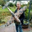
martin collins 1 Posted January 31, 2020 Share Posted January 31, 2020 Bought this little Flea a few months ago without any gear in it and have converted it to electric on 3s. I have the plans that came with it and am trying to balance it on the C of G, it will need quite a bit of lead. The question i have is unlike a plane with a long nose it is not obvious how much i need, is it enough when the tail wheel lifts before the mains? a lot of lead doesn`t really make a lot of difference and with the short nose it is not obvious how much is enough. What do you all do in this situation? Quote Link to comment Share on other sites More sharing options...
Robin Colbourne Posted February 1, 2020 Share Posted February 1, 2020 According to this Flying Flea Design Notes Henri Mignet started with the CofG at 41% of the front wing chord, and eventually moved it to 50%, so it may well be that if you are applying conventional aeroplane C of G rules, you've got it too far forward. Quote Link to comment Share on other sites More sharing options...
brokenenglish Posted February 1, 2020 Share Posted February 1, 2020 There are several Flea plans on Outerzone, it would be worth looking to see where they specify the CG. Quote Link to comment Share on other sites More sharing options...
martin collins 1 Posted February 1, 2020 Author Share Posted February 1, 2020 I have the plan and know the balance point, what i was asking was that when trying to balance it is not obvious how much lead is required due to the short nose a lot of lead seems to make little difference. Quote Link to comment Share on other sites More sharing options...
Peter Miller Posted February 1, 2020 Share Posted February 1, 2020 Quite frankly the only answer is to keep adding lead until it balances where the plan says it should. It CAN be calculated but don't ask me for the maths and the answer will be the same in the end, calculated or done empirically Quote Link to comment Share on other sites More sharing options...
Piers Bowlan Posted February 1, 2020 Share Posted February 1, 2020 The best thing to use to balance an electric model is quite clearly the battery. With surgery, and perhaps major surgery, is it possible to push the battery through the forward bulkhead so that it is under the motor with it's forward edge up against the front of the cowl? If the battery is sitting beneath the wing you could end up adding a lot of lead to the nose, which won't do much for the model's flying qualities. By the way which flea plan is it built from or don't you know, as you didn't build it? Looks nicely made. Quote Link to comment Share on other sites More sharing options...
martin collins 1 Posted February 2, 2020 Author Share Posted February 2, 2020 Battery now right up to the nose with some mods and lead added, the plan is labeled HM18 (Abbolt Baynes Modified), 1/5 scale Superplan. No designer is printed on the plan. Quote Link to comment Share on other sites More sharing options...
brokenenglish Posted February 2, 2020 Share Posted February 2, 2020 It's Bob Wright's design. Published in Radio Modeller December 1992, but his name is clearly printed under the plan title on my copy. Is it the original blue and red plan that you have, or has someone photocopied it? Edited By brokenenglish on 02/02/2020 21:13:56 Quote Link to comment Share on other sites More sharing options...
martin collins 1 Posted February 3, 2020 Author Share Posted February 3, 2020 Thanks, any advice for the maiden flight? The guy i bought it off said use the throttle more than the pivoting wing for changes in pich. Quote Link to comment Share on other sites More sharing options...
Piers Bowlan Posted February 3, 2020 Share Posted February 3, 2020 I have the plan and original RM article. Yes, Bob Wright says 'It is best to use the throttle to ascend and descend, regarding the stick as a trim control'. I am surprised how far forward the c of g is, considering it is a tandem wing aeroplane (78mm from the LE - approx. 30% MAC). Also an 'interesting' under cambered and reflexed wing section used, I can only assume that is what is used on the full sized? Yet another model that has been on my build list since I first bought the mag but the banana shaped wing put me off a bit so far! Looking forward to a full flight report Martin. Quote Link to comment Share on other sites More sharing options...
martin collins 1 Posted February 3, 2020 Author Share Posted February 3, 2020 Will certainly let you know how it flies, would you be able to scan the RM article and message it to me Piers, i only have the plan, i would be interested to read it..............Martin Quote Link to comment Share on other sites More sharing options...
PatMc Posted February 3, 2020 Share Posted February 3, 2020 I have a pdf of working drawings for the full size HM293 & HM360/380. They show the cg at 25% from the LE of front wing to TE of rear wing, which works out at 55% of front wing chord. Note the cg should be behind the front wing pivot point or the control will be unstable with "snatching" between any change in incidence. Below are the AM scale drawings of the HM14 & HM280. The HM280 is similar to the versions in the working drawings. PS for anyone interested in the full size working drawings they can be downloaded from here. Edited By PatMc on 03/02/2020 23:30:09 Quote Link to comment Share on other sites More sharing options...
Piers Bowlan Posted February 4, 2020 Share Posted February 4, 2020 Here is the RM article from Dec 1992. Sorry about the orientation of the top two photos, looked OK on my computer when I edited them Quote Link to comment Share on other sites More sharing options...
Piers Bowlan Posted February 4, 2020 Share Posted February 4, 2020 Not a lot of info in the article Martin but some nice photos. I tried to send a PDF scan by PM but I couldn't figure out how to attach it without your email address, so posted .jpg images instead. I suggest a nice calm day for the maiden - and wear bicycle clips! Edited By Piers Bowlan on 04/02/2020 15:59:01 Quote Link to comment Share on other sites More sharing options...
martin collins 1 Posted February 4, 2020 Author Share Posted February 4, 2020 Thanks very much for that Piers, it gives the wing movement as only 1/8" up and down and is that 2.9 16ths of an inch between the wings as in just under 3/16ths or am i misreading it?.............Martin Quote Link to comment Share on other sites More sharing options...
martin collins 1 Posted February 5, 2020 Author Share Posted February 5, 2020 Ok, i will answer my own question having looked at the plans again, 2" and 9/16 maximum gap between the trailing edge of the top wing and the top point on the bottom wing.................mine is set at 4" !!!! This leads me to believe that this model hasn`t flown before and i am not sure there is enough adjustment on the rods to pull it down that much, may have to make some new ones. Quote Link to comment Share on other sites More sharing options...
Piers Bowlan Posted February 6, 2020 Share Posted February 6, 2020 Martin. if you have a 4in gap between the TE of the forward wing and the top of the rear wing, then something is not quite right somewhere! Clearly the under surface of the forward wing should be approximately level with the under surface of the rear wing (maybe a couple of degrees positive incidence, max). If you are not sure, just tape a couple of strips of balsa under both wings and look at the side view of the wings - are they parallel? Looking at your photographs it might appear that the builder has lengthened the A frame support of the forward wing by about one and a half inches? This would make the gap between the TE and rear wing, 4in not 2 1/2in, as in your model. (2 and 1/2in is as near as dam-it 2 and 9/16in in my book!). In other words the builder has raised the forward wing by one and a half inches. So will it fly? Yes undoubtedly, I can see that it would not make much difference apart from raising the centre of drag a tad. So why would he do it? The original full sized Flea had an infamous design fault where at high angles of incidence (15 degrees) the airflow from the forward wing would interfere with the airflow over the rear wing causing a severe pitch down, which was not recoverable (shades of B737 MAX). One fix was to raise the forward wing. Pure speculation on my part but I think the builder of your model may have made this modification during his build. Just measure the length of the wire wing support, the forward wire will be about 5 1/4in and the rear 5in long, according to the plan. If they are significantly longer he has raised the forward wing. On the other hand I may be totally wrong! Edited By Piers Bowlan on 06/02/2020 08:22:51 Quote Link to comment Share on other sites More sharing options...
martin collins 1 Posted February 6, 2020 Author Share Posted February 6, 2020 At work at the mo so i can, t check it but i turned the servo round whch put it a lot closer, just 1/2" out. I adjusted the rods up and it is now the correct gap. Will check the pylon length later but it all looks ok visually, i think the photos may be deceptive. Quote Link to comment Share on other sites More sharing options...
martin collins 1 Posted February 6, 2020 Author Share Posted February 6, 2020 Measured the wire wing support, it is the same as on the plan, it is obviously the camera angle that makes it look larger............ Quote Link to comment Share on other sites More sharing options...
Peter Miller Posted February 7, 2020 Share Posted February 7, 2020 I have just been browsing through my library and found my book on the first home builts. I have found the complete set of instructions for building the Flying Flea as published by Newnes Practical Mechanics. I can find no reference to the CG location but the articles do not include a set of actual construction drawings. This book also includes the complete series of articles on building the Luton Minor, a much longer and more detailed series which does give the CG location The books is written/compiled by Arthur Ord-Hume who actually designed and built the Luton Minor Quote Link to comment Share on other sites More sharing options...
brokenenglish Posted February 7, 2020 Share Posted February 7, 2020 Peter, I didn't think it would be helpful, but I have a small collection (4) of Henri Mignet's original books, all published within the period 1928-34, in French of course. I don't know what printing techniques were used, but one of them is actually a "printed" version of Mignet's handwriting. Here are a couple of pages. Note that the plane illustrated isn't a Flea. That's because this particular book covers generic theory, applicable to all HM's designs. For those interested in the French language, the headings are: 1. Plywood 2. Strip wood 3. Covering fabric 4. Cellulose dope 5. Wheels 6. Metal fittings Edited By brokenenglish on 07/02/2020 10:36:27 Edited By brokenenglish on 07/02/2020 10:40:04 Quote Link to comment Share on other sites More sharing options...
William Macleod Posted February 5 Share Posted February 5 (edited) Hi Martin...did it ever fly. Just picked up a small one. Bill Edited February 5 by William Macleod Quote Link to comment Share on other sites More sharing options...

Recommended Posts
Join the conversation
You can post now and register later. If you have an account, sign in now to post with your account.
Note: Your post will require moderator approval before it will be visible.