Richard Leech 3 Posted June 6, 2023 Share Posted June 6, 2023 This is my first attempt at an online build log - so bear with me. I have built around 15 traditional balsa models since retiring from commercial aviation, so although I know a little bit, but I'm still learning !! I managed to acquire this Flair Cub from the local free cycle facebook page - the fuselage was part built, the foam core wings and all accessories were in the box!. It looks as if the local mice had eaten the plans and the ailerons, but for a freebee, had to give it a go. 1 Quote Link to comment Share on other sites More sharing options...
Richard Leech 3 Posted June 6, 2023 Author Share Posted June 6, 2023 Although a simple build, I found a set of plans on line, but unfortunately rather blurred, the significant information concerning CofG, and control surface ranges are inside a mouse somewhere, so if anyone can enlighten me, it would be most appreciated. I have already started started the refurbishment and electric conversion, so the time scale on the blog may seem a bit odd. Quote Link to comment Share on other sites More sharing options...
leccyflyer Posted June 6, 2023 Share Posted June 6, 2023 Hi Richard I do have the instruction sheets in my files and will get that information for you. I'll watch your thread with interest. Brian 1 Quote Link to comment Share on other sites More sharing options...
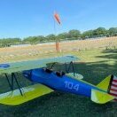
Richard Leech 3 Posted June 6, 2023 Author Share Posted June 6, 2023 My main concern was the original build as the box still had the original balsa cement in it, not that I was going to use it again, but I was concerned about the strength of the existing joints. I have also decided that the wings need to be attached by bolts not bands, the battery needs to be accessed from the top and finally to be in WW2 US army invasion livery. 1 Quote Link to comment Share on other sites More sharing options...
Richard Leech 3 Posted June 6, 2023 Author Share Posted June 6, 2023 Thanks Brian Quote Link to comment Share on other sites More sharing options...
leccyflyer Posted June 6, 2023 Share Posted June 6, 2023 4 minutes ago, Richard Leech 3 said: My main concern was the original build as the box still had the original balsa cement in it, not that I was going to use it again, but I was concerned about the strength of the existing joints. I have also decided that the wings need to be attached by bolts not bands, the battery needs to be accessed from the top and finally to be in WW2 US army invasion livery. I'd be flooding all of the joints in the liteply with Deluxe Superphatic - should be good as new after that. My Flair Cub was destined to be modified into a Wagner Twin Cub - two fuselages - but I got interested in other things. 1 Quote Link to comment Share on other sites More sharing options...
leccyflyer Posted June 6, 2023 Share Posted June 6, 2023 You're in luck - I have an almost complete spare set of instructions - half-a-dozen large format A2-ish printed sheets, the model doesn't come with a plan. If you would like them, just drop me a PM with your address and I'll pop them in the post. In the meantime the information you asked for is below. CG - 85mm from the leading edge at the wing root. Ailerons - 8mm up, 6mm down Elevator - 20mm each way Rudder- 20mm each way. 1 Quote Link to comment Share on other sites More sharing options...
Richard Leech 3 Posted June 6, 2023 Author Share Posted June 6, 2023 Thanks leccyfler have PM you. So - electric set up ? I've gone for a 4250-800 with 12x6 APC and 4S 3300-3700 mah - CofG will determine battery size. Also decided on dual aileron servo's and a Seagull Cub UC (SEA74) which doesn't quite fit (but will) and looks a bit more authentic. 1 Quote Link to comment Share on other sites More sharing options...
Richard Leech 3 Posted June 6, 2023 Author Share Posted June 6, 2023 The original build IC configuration needs adapting to suit electric conversion. I have invested in a Carbon Copy GF cowling which will allow a bit of hidden modification. After measuring the position of the engine bearers, it was noted that the thrust line is very high relative to the cowling, hence IC models had the cylinder head sticking up soooo high, it didn't look quite right!! Interestingly enough, a 42mm diameter motor is still going to very tight within the cowling. Quote Link to comment Share on other sites More sharing options...
Richard Leech 3 Posted June 6, 2023 Author Share Posted June 6, 2023 First job was to clean the fuselage. A light rub down seemed to clean the mouldy residue, although the light ply seemed very dusty. Thinking I might need to coat in sanding sealer later. The wings were still in the original packaging (foam) and showed no obvious problems (the mice didn't get at them) I don't know how old this kit is - any ideas? Quote Link to comment Share on other sites More sharing options...
Jim Hearnden 1 Posted June 6, 2023 Share Posted June 6, 2023 I flew several IC versions of the Flair kit a few years back. All came out very tail heavy & needed a lot of church roof to get the CG anywhere near right. They are very unpleasant to fly even slightly tail heavy. 1 Quote Link to comment Share on other sites More sharing options...
leccyflyer Posted June 7, 2023 Share Posted June 7, 2023 The Flair Cub was around and well established when I came back into the hobby in 1993, so I'd guess late 80's. You're very lucky that the mice had the instruction sheets rather than the foam wing. They love a bit of foam, especially wheels, but also fuselages and wings. That can be a real problem with shed or barn storage if the little beggars get in. 1 Quote Link to comment Share on other sites More sharing options...
David Davis Posted June 7, 2023 Share Posted June 7, 2023 I had a couple of these in the Nineties, both abandoned projects. Both flew well powered by an Enya 40 and I don't recall having to put a lot of lead in the nose. 1 Quote Link to comment Share on other sites More sharing options...
Geoff S Posted June 7, 2023 Share Posted June 7, 2023 (edited) 3 hours ago, leccyflyer said: The Flair Cub was around and well established when I came back into the hobby in 1993, so I'd guess late 80's. You're very lucky that the mice had the instruction sheets rather than the foam wing. They love a bit of foam, especially wheels, but also fuselages and wings. That can be a real problem with shed or barn storage if the little beggars get in. They'll eat anything, even stuff with no nourishment at all like nylon pannier bags and a brand new, yet to be used, rucksack in my case. They also chewed the plastic water pipes under our shower which we replaced with copper - that'll break their teeth! Edited June 7, 2023 by Geoff S 1 1 Quote Link to comment Share on other sites More sharing options...
Richard Leech 3 Posted June 7, 2023 Author Share Posted June 7, 2023 (edited) Having looked closer at the fuselage and wiggled all the joints it was evident that re-glueing was required, I used Titebond aliphatic over all the joints apart from the stab which when wiggled came out ! Still feeling a little unsure about the original glue adhesion, I added 6mm square light balsa between the frames upper and lower fuselage and added triangular section to the vertical face of the frames. This also allowed to create a radius at the edges. Edited June 7, 2023 by Richard Leech 3 2 Quote Link to comment Share on other sites More sharing options...
Richard Leech 3 Posted June 7, 2023 Author Share Posted June 7, 2023 Control snakes were added as the rod and wire method seemed a bit dated. I have added a bit of weight by these changes, so hoping the CofG will be OK. 1 Quote Link to comment Share on other sites More sharing options...
Richard Leech 3 Posted June 7, 2023 Author Share Posted June 7, 2023 The cockpit frame was also beefed up as I has read that this was a weak point. 1 Quote Link to comment Share on other sites More sharing options...
Richard Leech 3 Posted June 7, 2023 Author Share Posted June 7, 2023 A new frame was required to support the fwd wing locating peg made from 4mm ply and a rear wing support bracket holding 5mm T nuts for the wing attachment bolts. The new frame was attached to the existing frame. 1 Quote Link to comment Share on other sites More sharing options...
leccyflyer Posted June 7, 2023 Share Posted June 7, 2023 Interesting - is that 4mm birch ply or 4mm liteply that you are using for that wing peg retaining former Richard? Quote Link to comment Share on other sites More sharing options...
Richard Leech 3 Posted June 7, 2023 Author Share Posted June 7, 2023 2 hours ago, leccyflyer said: Interesting - is that 4mm birch ply or 4mm liteply that you are using for that wing peg retaining former Richard? Birch ply - I really don't like lite ply for anything structural. 1 Quote Link to comment Share on other sites More sharing options...
Engine Doctor Posted June 7, 2023 Share Posted June 7, 2023 Richard you mention mould growing on balsa and light ply when you aquired the kit. Please be very careful when sanding it off as it can make you very ill. It happened to me years ago when i bought a Cambria Me 109 kit that had been damp . When I opened the box it had a green mould all over it. Never thought about it and just sanded it off and built the kit. Few days later had very bad chest and felt dreadful. Fortunately you could see a doctor back then very easily. 1 Quote Link to comment Share on other sites More sharing options...
Richard Leech 3 Posted June 7, 2023 Author Share Posted June 7, 2023 Thanks Engine Doctor, I did wear a mask, but good info for those reading the blog. Quote Link to comment Share on other sites More sharing options...
Richard Leech 3 Posted June 7, 2023 Author Share Posted June 7, 2023 Looking at the idea of a top loading battery access, it became clear that there was not enough room between the windshield and engine bulkhead to make a suitable access cowling, therefore a cowling combining the windshield between the wing support frame and the engine firewall had to be made. The frame between the engine bulkhead and wing support frame had the top removed and spruce longerons fitted either side of the bay to create the new battery compartment. Quote Link to comment Share on other sites More sharing options...
Richard Leech 3 Posted June 7, 2023 Author Share Posted June 7, 2023 (edited) The new removable cowling uses magnets to secure it and also encompasses the wing leading edge fairing. The slot at the rear of the fairing allows protrusion of the wing peg through the support frame and also positions the cowling centrally. Edited June 7, 2023 by Richard Leech 3 1 Quote Link to comment Share on other sites More sharing options...
Richard Leech 3 Posted June 9, 2023 Author Share Posted June 9, 2023 As mentioned, I have planned to fit a 4250 sized outrunner motor to power the aircraft. The existing engine bearers and cowling are going to serve no purpose as a new fwd bulkhead will be required and a new GF cowling is going to be used. The prop disc distance to the bulkhead is around 90mm, so I have plenty of room to space the motor from the bulkhead. Considering the 4250 motor is going to be lighter than an IC engine, I didn't worry too much about additional building weight at the front. The existing front was cut 10mm fwd of the fwd bulkhead to allow an attachment surface for the new cowling. Quote Link to comment Share on other sites More sharing options...

Recommended Posts
Join the conversation
You can post now and register later. If you have an account, sign in now to post with your account.
Note: Your post will require moderator approval before it will be visible.