Jon H Posted August 9, 2019 Share Posted August 9, 2019 Posted by cymaz on 09/08/2019 14:02:10: Posted by Jon - Laser Engines on 09/08/2019 13:56:36: Posted by cymaz on 09/08/2019 13:34:53: And, finally, the CG is incorrect on the plan I balanced mine at the marks on the plans and its spot on :\ Bert, its the cabanes that are the issue as the top spar ends just outboard of them so the cabanes do not take any of the lifting loads. Its all transmitted to the lower wing through the interplane struts. I will probably extend the spar on the next one and use some sort of steel plate for strut attachment. I balanced mine and it was wayyyy tail heavy. It’s in the blog somewhere. I have no doubt. Mine balances about on the rear bolts for the top wing i think. At this point it sits slightly nose down as i would expect a biplane to sit. The tail on mine has +ve incidence (down trim) and i fly it with further down trim on the elevator. Quote Link to comment Share on other sites More sharing options...
bert baker Posted August 9, 2019 Share Posted August 9, 2019 Can agree on cabaines being removable.. I have another Stampe that has suffered a crash and the cabaines are slightly twisted,And a small bent where it disappears into the fuz. To awkward to straighten, I plan to cut all the cabaine wires and slide brass tube over them and jig the wing into plane and silver solder the tubes to the wires Quote Link to comment Share on other sites More sharing options...
Jon H Posted August 9, 2019 Share Posted August 9, 2019 Bert the issue comes from the top spar ending outside of its support. As lift builds on the wing the lower spar is in tension but as its end is not connected to anything it is not restrained very well and the wing bends quite easily. The flat ply crutch thing in the middle of the centre section is supposed to take the load but i have found it pretty useless. If its too late to mod the structure adding rigging will sort it. Sadly my rigging points are not strong enough for real rigging so i just have to fly gently. Lets not forget that the model was designed around a merco 61 and was expected to be half the weight of most of ours so we are putting quite a bit more stress on it than it was probably designed for Quote Link to comment Share on other sites More sharing options...
John Bisset Posted August 9, 2019 Share Posted August 9, 2019 Looking at my plans for the Precedent Stampe, measuring the tailplane incidence (lower surface of tailplane) with reference to the upper fuselage longerons, which make a ~ good level reference, the tailplane measures at 4 degrees nose up. (That sounds a lot. Mine is a kit from ~30 years ago, still not built. I will have to hunt around for an instrcution booklet; it's not in the box, so I must have taken it out to dream over.) It's not so easy from the plans to determine wing incidence accurately. Looking at the plan and making my best guess of chord line, then transposing that up using (nautical !) parallel rules,the lower wing incidence appears to be around 5.5 degrees nose up. I'd suggest both my figures are +/- around 0.5 degree. Does that help? I think both wings should have the same incidence at the root. I have an aircraft engineer friend who is rebuilding a full size Stampe right now, and is close to re-assembling wings and tailplane. I could ask him what the values should be, though the model values may differ. I think his son has a Precedent Stampe part built. Quote Link to comment Share on other sites More sharing options...
John Bisset Posted August 9, 2019 Share Posted August 9, 2019 Jon, that sounds like the model needs the same tie rods for the lower wings as the real thing ! Quote Link to comment Share on other sites More sharing options...
bert baker Posted August 9, 2019 Share Posted August 9, 2019 Hmm there’s many a Stampe out there with out rigging,and it was Not fitted as standard nor is the new kit. I did ask as the display model at Slec stand Does have rigging, I was interested as at that point I hadn’t made the brackets, these have all been made my lad did a loop at full throttle with one that had no rigging and the wings snapped.. But this was on a very old beaten up one so no real supprize I was fly with a chap who has a really nice example of a Stampe, up front is a SC four stroke Don’t know size, it to wasn’t fitted with rigging. Edited By bert baker on 09/08/2019 16:29:02 Edited By bert baker on 09/08/2019 16:32:15 Edited By bert baker on 09/08/2019 16:32:56 Quote Link to comment Share on other sites More sharing options...
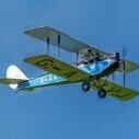
Richard Acland Posted August 9, 2019 Share Posted August 9, 2019 I found that although I built the correct amount of tail incidence on my Precedent Stampe I still need a massive amount of down elevator to achieve level flight. This model flies quite well using an SC 90 FS Edited By Richard Acland on 09/08/2019 19:14:42 Quote Link to comment Share on other sites More sharing options...
Martin McIntosh Posted August 9, 2019 Share Posted August 9, 2019 Thanks Richard, probably the same copy of the one which I used. These pics show it I think. Edited By Martin McIntosh on 09/08/2019 19:28:08 Edited By Martin McIntosh on 09/08/2019 19:29:11 Quote Link to comment Share on other sites More sharing options...
Martin McIntosh Posted August 9, 2019 Share Posted August 9, 2019 Thanks John B. Very helpful. Quote Link to comment Share on other sites More sharing options...
cymaz Posted August 9, 2019 Author Share Posted August 9, 2019 Same here...huge down elevator needed Quote Link to comment Share on other sites More sharing options...
Nick Santovito Posted August 10, 2019 Share Posted August 10, 2019 Posted by Martin McIntosh on 09/08/2019 15:08:47: Whilst people are digging out their plans I would greatly appreciate it if someone would measure the incidence between, say, the tail and the top wing. I have heard that some versions of the plan show the wrong tail incidence, and guess which one I built. My elevator has to droop by some 20deg. but does not seem to affect the flying. Nothing I can do about it now but it would just be nice to know since with each side built from 1/4sq. spruce over the plan it would be difficult to get it wrong. Hi Martin. I measured my plans with a protractor during the build and came up with the following: With the fuselage thrust line at 0.... Top wing 4 degrees positive. Bottom wing 5 degrees positive. Stab. 5 degrees positive. CG: balances at the rear bolt of the top wing, I've flown as far back as the TE of the center section, but sometimes it takes 3 or 4 turns to come out of a spin. Hope this helps. Nick Quote Link to comment Share on other sites More sharing options...
Martin McIntosh Posted August 10, 2019 Share Posted August 10, 2019 Yours sounds more like correct Nick. It would seem that I am not alone with the massive amount of down. Was beginning to doubt my own building skills. Quote Link to comment Share on other sites More sharing options...
Nick Santovito Posted August 10, 2019 Share Posted August 10, 2019 Was digging thru the old photos and found a couple that might be helpful for those who want to add rigging. I used brass strips - about 1/64" - bent and drilled to accept Dubro clevises on one end as the plans show but with one extra hole for the wire clevis, and 1/2" servo screws on the other and just screwed them to the interplane strut mounts but sideways to the plans view , then soldered the uppers to the cabane struts. Finally recessed the lower wing saddle for the lower point and epoxied it in. I know I'm a hacker but I believe you could pretty this up a good bit. Use 125lb clear nylon coated fishing leader for the wires. It's held up for the last five years of rather bad flying. I wish I had thought of mounting the gear on the bottom while building. I have my fuel tank exiting between the top of the forward struts and the bottom of the firewall extension. Could have mounted a bigger tank. Edited By Nick Santovito on 10/08/2019 15:07:06 Quote Link to comment Share on other sites More sharing options...
bert baker Posted August 11, 2019 Share Posted August 11, 2019 Quote Link to comment Share on other sites More sharing options...
bert baker Posted August 11, 2019 Share Posted August 11, 2019 Have been making some bits for the rigging wires. the long piece screws to top of bottom wing, and will exit either side of the fuz. two flying wires will go to the front top strut brackets. I still have the rear top brackets to make, I recall Cymaz using wings or parts of wings cut by Falcon Aviation. i am intriguied as to what the difference is between the new kit and the Falcon parts, I still have a origional die crushed kit that I have been keeping for prosperity, I do fancy the look of the laser cut parts, Quote Link to comment Share on other sites More sharing options...
bert baker Posted August 11, 2019 Share Posted August 11, 2019 The following measurments have been taken from a part built Precedent Stampe I purchased a while ago, its in need of work but should be ok. the cabaines haven’t had support wires fitted qnd at the moment the top wing ply plate won’t sit flat on the top of the cabaines Quote Link to comment Share on other sites More sharing options...
bert baker Posted August 11, 2019 Share Posted August 11, 2019 Top wing above +2.5 Quote Link to comment Share on other sites More sharing options...
bert baker Posted August 11, 2019 Share Posted August 11, 2019 Quote Link to comment Share on other sites More sharing options...
bert baker Posted August 11, 2019 Share Posted August 11, 2019 Bottom wing +5.5 Quote Link to comment Share on other sites More sharing options...
bert baker Posted August 11, 2019 Share Posted August 11, 2019 Quote Link to comment Share on other sites More sharing options...
bert baker Posted August 11, 2019 Share Posted August 11, 2019 Tail +5 degrees Quote Link to comment Share on other sites More sharing options...
bert baker Posted August 11, 2019 Share Posted August 11, 2019 Top longeron was set to zero and measured at the cockpit as it has a door that folds down Quote Link to comment Share on other sites More sharing options...
bert baker Posted August 13, 2019 Share Posted August 13, 2019 Cymaz,,, info on Falcon wing parts please Quote Link to comment Share on other sites More sharing options...
cymaz Posted August 13, 2019 Author Share Posted August 13, 2019 Bert, I used Richard Hughes at Falcon Aviation. HERE is the old website....I don’t know if he is still going. I hope he is, he was very helpful and always willing to get the job done Quote Link to comment Share on other sites More sharing options...
bert baker Posted August 13, 2019 Share Posted August 13, 2019 Hi yes spoke to them this morning, What was you reason for going the laser cut route,,, I can see the point if you have smashed wings. and can see that the laser cut spar is nice,, its not a cheap option. Quote Link to comment Share on other sites More sharing options...

Recommended Posts
Join the conversation
You can post now and register later. If you have an account, sign in now to post with your account.
Note: Your post will require moderator approval before it will be visible.