Geoff Gardiner Posted December 1, 2016 Author Share Posted December 1, 2016 Bit more done: I remembered to fit some draw strings, for pulling through the servo cables, before fitting the bottom wing sheeting. Next, I added the leading edges and planed/sanded to profile. I then traced the wingtips from the plan and cut out a pair, glued them on and sanded them to profile. Then, I made up a couple of ailerons, cut from the plan. Finally, I have glued in the nacelles and cut out the end tips - traced from the plan. I couldn't find any mention of these in the build instructions. More later... Quote Link to comment Share on other sites More sharing options...
Geoff Gardiner Posted December 3, 2016 Author Share Posted December 3, 2016 I tried gluing on the nacelle end tip, by eye, but it looked completely wrong and I had to cut it off. I then had the bright idea of using the plan to make a little jig that would give the correct angle. I then added formers N5 - N8. More later... Quote Link to comment Share on other sites More sharing options...
Broken Prop Posted December 3, 2016 Share Posted December 3, 2016 Lovely work Geoff. I can't wait to see the finished item! Quote Link to comment Share on other sites More sharing options...
Geoff Gardiner Posted December 4, 2016 Author Share Posted December 4, 2016 Thanks Broken Prop. I have started to add the nacelle sides. I decided it might be more manageable to do them on side at a time - I may be proved wrong!. I have also been hunting around for some ammonia to help with the bending. I looked for ages and managed to find this in a shop called Robert Dyas. What sort of concentration do people use? Geoff... More later... Quote Link to comment Share on other sites More sharing options...
Martin McIntosh Posted December 4, 2016 Share Posted December 4, 2016 Just use it neat then run away like hell until the eye watering stench subsides. Some water added after about 10 mins. helps. Best of luck with wood that thick. Can`t remember what I used but it looks like 3/16. The rear end was done with several pieces of block if my memory serves me correctly. Quote Link to comment Share on other sites More sharing options...
Geoff Gardiner Posted December 8, 2016 Author Share Posted December 8, 2016 Hi everyone. I am at the point where I need to sheet the top and bottom of the nacelles. Before I do this, I need to decide where I am going to install the ESC’s. I am considering two options: 1 – The plan shows the ESC’s in the top of the nacelles, just behind the firewall (N2). I feel that putting them here is going to give access problems and would be quite tricky to connect up to the motor. It may require making an access hatch in the top of the nacelles. Also I would have to extend the ESC to battery wires, which I believe will involve adding a capacitor. 2 – The other option would be to extend the motor to ESC wiring and put them in the main body of the fuselage. This should make access much easier but I am not sure how much space, in the fuselage, there will be to fit them in. I believe that there are several people on this forum that have built/are building the Mossie (Martin and Martian have build logs). I would be keen to know what you have done with your ESC’s/wiring and if you put in any extra hatches. Many thanks. Geoff… Quote Link to comment Share on other sites More sharing options...
Chris Walby Posted December 8, 2016 Share Posted December 8, 2016 Hi, I am a bit of a mosquito fan (PZ & BH ones) + TN DC3 & TN Vulcan (twin pusher) has resulted in rather a lot of research regarding twins with ESC's ! So PZ put theirs between nacelle & fuselage, where the radiators are on full size which allows for cooling/access and a compromise between longer motor/ESC leads and ESC/Battery leads. My DC3 has the ESC's behind the motor mounting & have ended up with long ESC/Battery leads (research has indicated this is not a good idea, but the manufacture of my ESC's has assured me there will be no issue/no need to add capacitors). My Vulcan has the ESC's at the front, next to the batteries and +3ft to the motors at the back.(running 4S 5000mAh, 60A ESC's and out runners). IMHO access and cooling is imperative, secondary would be which leads need to be extended, but go for longer ESC/motor leads as preference. And lastly a conversation with the ESC/motor manufacturer may prove helpful, but I would not add capacitors unless specifically instructed by ESC manufacturer...in my book the more links in the chain the more likely one will break!....and it only takes one link to fail to need the bin liner and a long walk! Hope this helps, if not please ask PS I read with interest as it will most likely be my next major build.......but when Jon (Laser engines) posted with a plan/engine over laid I nearly converted to the dark side! (IC must be the dark side as its not electric "light"!). Quote Link to comment Share on other sites More sharing options...
Martian Posted December 8, 2016 Share Posted December 8, 2016 Hi Geoff, she's coming along nicely, I figured the ESC in the nacelle has no advantage the spinner is or should be perfectly inline with nacelle therefore no cooling airflow so I have opted to place them in the nose there is more free airspace and no potential heat from the motors and access will be easy through the bomb bay doors it's a simple matter to extend the motor wires and the motor can be withdrawn from the nacelle front complete with wires, anyway that's what I'm proposing to do time will tell if she gets airborne and comes down in flames 😀 , must update my build Quote Link to comment Share on other sites More sharing options...
Martin McIntosh Posted December 8, 2016 Share Posted December 8, 2016 Hi guys, there seem to be a lot of options out there. Firstly, there is very little room in the fus after all the connectors etc have been fitted, and certainly none in the nose because the batteries are already a tight squeeze. I connected my esc`s directly behind the motors. I pondered over accessibility but with the spinners removed this is not a problem so I went for the added capacitor solution as recommended by all esc manufacturers: this is quite easy to do and there are pics on my build blog. I rarely provide any cooling for esc`s, indeed my Vulcan has them where they are outside the ducts but no air flowing over them. If you use an overkill size then they are doing very little work and only get slightly warm. The Vulcan uses 30A ones. My latest top secret project will use a quad unit in the fus, simply extending the motor wiring so that no caps would be needed anyway. These will be run close to the limit but are as yet untested. Quote Link to comment Share on other sites More sharing options...
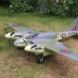
Geoff Gardiner Posted December 10, 2016 Author Share Posted December 10, 2016 I forgot to post the following picture. Before I started working on the nacelles I put all the bits together, for the first time, to get an idea of what it looks like. It's a bit of a monster - my biggest model so far. NB. The vertical stabilizer is just balanced on and is not in the correct position. Quote Link to comment Share on other sites More sharing options...
Martian Posted December 10, 2016 Share Posted December 10, 2016 she certainly is looking good and you must be pleased your taking her to bed with you 1 Quote Link to comment Share on other sites More sharing options...
Geoff Gardiner Posted December 11, 2016 Author Share Posted December 11, 2016 Carrying on with the nacelles, I glued on the other side: I then brushed on some neat ammonia, left it for 10 minutes, soaked with water (using a brush) and then clamped it up. After it had all dried I removed the clamps and it pretty much stayed in position. I think using ammonia is a good method, if you can get past the smell. I then glued everything up and re-clamped. Before I can go any further with the nacelles, I need to decide what I am going to do with the ESC's. I have recently had an ESC catch fire in my Chipmunk. Luckily I was able to put it out immediately and saved the plane from going up in flames. For this reason, I am favouring putting the ESC's in the fuselage where they can be easily accessed. So my next job was to fill and sand the fuselage and cut out the bomb bay hatch to see how much room I have to play with. More later... Quote Link to comment Share on other sites More sharing options...
Geoff Gardiner Posted December 13, 2016 Author Share Posted December 13, 2016 I have made a bit of a boo…boo… Having measured and checked for correct alignment, I epoxied the main phenolic tube into the fuselage. I am not quite sure what happened but once it had cured I offered the wings up. It was obvious that the angle was wrong, as the wing roots didn’t sit flush against the fuselage. Using a drill and a hack saw blade, I carefully released one end of the tube and moved it forward a few millimeters. I then cut a spacer and glued it in. It’s not pretty but now the wings sit flush with the fuselage. You live and learn! More later. Geoff… Quote Link to comment Share on other sites More sharing options...
Martin McIntosh Posted December 14, 2016 Share Posted December 14, 2016 You are not alone. A current o/d project just did not look right somehow. On measuring the wing to tail distance I discovered that it was 3/4" short! The tubes are alloy, well and truly thick ca`d in. Several hours and half a bottle of debonder later I got them out. Quote Link to comment Share on other sites More sharing options...
Martian Posted December 14, 2016 Share Posted December 14, 2016 oh B********* at least you were able to save it and brave to publish your error and if it really worries you box it in Quote Link to comment Share on other sites More sharing options...
Geoff Gardiner Posted December 15, 2016 Author Share Posted December 15, 2016 I happened by this video from Canada about aircraft with Merlin engines. It's a bit long but has some great flying footage of their Mossie. Enjoy... Edited By Geoff Gardiner on 15/12/2016 17:19:07 Quote Link to comment Share on other sites More sharing options...
Martin McIntosh Posted December 15, 2016 Share Posted December 15, 2016 Brilliant footage. Thanks. Quote Link to comment Share on other sites More sharing options...
Allan Bennett Posted December 15, 2016 Share Posted December 15, 2016 Thanks for posting that Geoff. Quote Link to comment Share on other sites More sharing options...
Geoff Gardiner Posted January 14, 2017 Author Share Posted January 14, 2017 It's been a bit slow going on the nacelles but here is a sequence of pictures to show where I am up to: More later... Quote Link to comment Share on other sites More sharing options...
Martian Posted January 15, 2017 Share Posted January 15, 2017 Coming along nice Geoff Quote Link to comment Share on other sites More sharing options...
Geoff Gardiner Posted January 28, 2017 Author Share Posted January 28, 2017 Still plodding along with the nacelles: Getting there slowly. More later... Quote Link to comment Share on other sites More sharing options...
Martin McIntosh Posted January 28, 2017 Share Posted January 28, 2017 Not as easy as they may look, are they. Great work so far. Quote Link to comment Share on other sites More sharing options...
Geoff Gardiner Posted February 5, 2017 Author Share Posted February 5, 2017 I was expecting to have problems fitting the retracts and I wasn't disappointed. They are too long and a bit too wide where the nacelle tapers. I trimmed back the rear of the nacelle, which helped a bit but the width was still an issue. After much deliberation, I decided to bite the bullet and shorten the oleo struts by 15mm. I then had to drill and tap to move the stop screw. A much better fit. Fingers crossed that there will still be enough prop clearance with the ground. Cutting clearance holes in the wing next. More later... Quote Link to comment Share on other sites More sharing options...
Martin McIntosh Posted February 5, 2017 Share Posted February 5, 2017 So glad to hear that you are having as much fun as I did with this bit. I think I posted earlier that the interesting stuff was yet to come. Those wheels look very wide in the pics. I used HK ones in the end, apparently about the same weight as Tony`s. I toyed with the idea of using HK narrow ultra light ones but they have a square section and would need turning down to fit. I ground some material from the inside of the oleos to narrow them a bit but of course then had to make up new yokes. When cutting the wing for clearance I needed to remove a section (all of it) of the spruce rear top spar. Keep at it, it is worth the effort. Quote Link to comment Share on other sites More sharing options...
Martian Posted February 5, 2017 Share Posted February 5, 2017 Nice going Geoff, Don,t forget to measure the clearance needed for the uc doors as they may need to be made deeper Quote Link to comment Share on other sites More sharing options...

Recommended Posts
Join the conversation
You can post now and register later. If you have an account, sign in now to post with your account.
Note: Your post will require moderator approval before it will be visible.