Jon H Posted December 15, 2017 Share Posted December 15, 2017 Thats nice and neat Ron, i like it. Do you want/need the longer exhaust or will you use a silicone thingy? Quote Link to comment Share on other sites More sharing options...
Ron Gray Posted December 15, 2017 Share Posted December 15, 2017 Thanks Jon. I think I’ll use a very short length of silicone, if I had the longer exhaust I’d have to cut it! Quote Link to comment Share on other sites More sharing options...
Tim Flyer Posted December 19, 2017 Share Posted December 19, 2017 Hi all . I’m starting to make some progress on the wings now. I’m pleased the kit came with the extra instructions for the retracts. I’m using the retract plates in the kit (slightly modified)as they seem quite solid. Like Bob did I plan to put some extra bearers below to allow a key for the screws and to provide rigidity. The plate also has peg holes to key it into the foam which I will also use. I have sloped the plate foam mount forward as much as possible. The hot wire was great I made a Little wooden handle for mine which helped. I’m lining the sides of the retract boxes with 1/8 balsa as per instructions. I think gorilla glue will be best in this area as it will fill any voids in the foam. In using some beefy metal HK retracts, hopefully the plane will still fly😊. I’m not sure whether I will use the plastic liners for the wheel and oleo cut outs, I think I will just use balsa. After I get this done which might be a while I will start on the flaps. I haven’t noticed any plans for those so far but I’m happy to improvise. I will get some more photos posted up soon. 😊 Quote Link to comment Share on other sites More sharing options...
Ron Gray Posted December 19, 2017 Share Posted December 19, 2017 Slow progress on mine, I’m still working on the fus. I’ve fitted a tank platform plus have fitted the 3 servos for the throttle, elevator and rudder. Like Tim I’m planning to use a ‘pull / pull’ system for the rudder but will also be connecting this to a steerable tailwheel. I was going to hide the control horn for the elevator but have now decided not to bother and to leave it exposed. Had a tentative trial fit of the rudder components and can see that there will be gaps to be filled as others have found, all part of the fun of building this ‘plane. Richard delivered the retracts and oleos yesterday, nice bits of kit, so nothing to stop me progressing with the wing once the fus is done. Very interested to see how you do the flaps Tim, I still haven’t decided if I’m going down that route yet but plenty of time to decide on that. One thing I want to do on all hinges is to make them concealed using Robert type hinges. Quote Link to comment Share on other sites More sharing options...
Bob Cotsford Posted December 19, 2017 Share Posted December 19, 2017 Here's a photo of the plastic wells Tim, I found they were about 3/4" too deep so I cut that much off the bottoms and inserted the cut-off portion into the remainder, they fitted quite neatly, at least I'm happy with the result The dotted lines are guides for glassing on the bandage. I've cut out the cockpit using Richard's suggestion of drawing around the canopy then cutting 1/4" above this line for the rear. I did the same for the front but this puts the instrument panel too far forward so now I'm putting wood back on! I removed all the foam back to the instrument panel bulkhead and lined the veneer with two layers of 1/6" soft sheet to stiffen it up. I've also added 1/32" ply pads so that I can use some tiny screws for additional canopy security. Getting the canopy centred to draw around it was a case of measure three times, draw twice, cut once Quote Link to comment Share on other sites More sharing options...
Bob Cotsford Posted December 19, 2017 Share Posted December 19, 2017 I've gone the fixed tailwheel and no flaps route, I've never yet found flaps to be that effective on this size of sports scale model. The rudder - what fun! I did mine like this: Glue on the rudder post, this holds everything together for the next stage. Cut a wedge out of the foam 1/8" wide at the front tapering back to nothing at the rudder post, adjust the wedge size to match your fuselage top deck. Pump some glue of choice into the gap formed and clamp the front of the rudder together. Next add the leading edge then finally slot the bottom of the rudder and wedge the lower front to adjust the width to match the rudder section to that of the top deck. Quote Link to comment Share on other sites More sharing options...
Tim Flyer Posted December 19, 2017 Share Posted December 19, 2017 That looks great Bob . Hmm I think I will use the plastic wheel wells too . I like your cockpit. Hi Ron your build looks neat too....I will be using a steerable tail wheel too but just a sport type like on the Acrowot that I will link to the bottom of the rudder which will move it directly. once I have the wings in place I will do more on the front end too but I wanted too see them fit first. I do like flaps so will be fitting them ...maybe oversized as my plane will probably be heavy 😉. I remember my rudder being a bit of a fiddle too but that’s all complete now. Edited By Timothy Harris 1 on 19/12/2017 11:48:09 Edited By Timothy Harris 1 on 19/12/2017 11:52:12 Edited By Timothy Harris 1 on 19/12/2017 11:53:48 Quote Link to comment Share on other sites More sharing options...
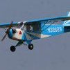
Ron Gray Posted December 19, 2017 Share Posted December 19, 2017 This is my fin, showing the gap under the elevator behind the crutch, easily filled. And the amount of the fin that will need to be brought in to line up with fus Also some shots showing the servo and tank installation. I’m thinking of mounting the Rx battery on the crutch between F1 and F2 Quote Link to comment Share on other sites More sharing options...
Bob Cotsford Posted December 19, 2017 Share Posted December 19, 2017 645Mgs? I'm just using 148s in the fuselage. I extended the front of the tailplane so that the sweep marries up with the fuselage. My fin is also about 1/16" shorter than the sides, I'll just put some sheet between the fin and fuselage top when I fit it. Edited By Bob Cotsford on 19/12/2017 15:16:24 Quote Link to comment Share on other sites More sharing options...
Ron Gray Posted December 19, 2017 Share Posted December 19, 2017 Servos not necessarily the ones I will be using but they were closest to hand when I cut everything out and drilled mounting holes! Looks like your fun sides are longer than mine and line up with the rudder post. I'll need to add a bit of rudder post plus some scrap to make up the length on mine. Your fin looks narrower than mine as you say, you need to fill that bit in whereas I need to reduce mine! The elevator on mine needs to have its LE recut to a different angle so that it intersects the fus, again no biggie. To be honest this is what I like about this build, having to work out odd bits as you go along but remembering to look ahead! Quote Link to comment Share on other sites More sharing options...
Tim Flyer Posted December 19, 2017 Share Posted December 19, 2017 I mounted my whole fin and tail further back and ran a 1 piece tailpist all the way from top to bottom so my plane might be half an inch longer 😉. I don’t think it will matter but made the tail easier to marry up with the rear deck . I did have to add some Wood fillets though. Edited By Timothy Harris 1 on 19/12/2017 19:21:50 Quote Link to comment Share on other sites More sharing options...
Jon H Posted December 19, 2017 Share Posted December 19, 2017 Posted by Timothy Harris 1 on 19/12/2017 16:39:18: I mounted my whole fin and tail further back and ran a 1 piece tail post all the way from top to bottom so my plane might be half an inch longer 😉. I don’t think it will matter but made the tail easier to marry up with the rear deck . I did have to add some Wood fillets though. Edited By Timothy Harris 1 on 19/12/2017 16:41:30 If anything you will end up with better directional stability which is a weakness of the La7. Even the full size suffered and my larger model will tail wag if flown excessively fast just like the full size did. During the war they didnt change it as fighter aircraft that are 100% stable dont dogfight very well! Quote Link to comment Share on other sites More sharing options...
Tim Flyer Posted December 19, 2017 Share Posted December 19, 2017 Cheers Jon I had wondered why the kit tail post seemed short, but I just laminated a couple of strips of balsa sheet I had handy. My plane isn’t going to be the most scale but I’m building for maximum practicality too. Anyway happy building. By the way Jon I see a “Jon Harper “ has been credited with the article in this months RCM&E on building a Chief Okinosh. I think they mean John Harper from Canada that they introduce on the contributors page ....anyway it’s electric... no laser engines in that 😉 Quote Link to comment Share on other sites More sharing options...
Tim Flyer Posted December 19, 2017 Share Posted December 19, 2017 Here is the first cut out in its way . I cut the initial hole with a large hole saw then enlarged it using the excellent perms grit curved surface sanding blocks . They give a smooth surface even on foam . My oleos have cantilevers so the channels have to be shaped . I have got to decide where to run the retract wire . I won’t bury it too much in case the retracts need replacement. Quote Link to comment Share on other sites More sharing options...
Bob Cotsford Posted December 20, 2017 Share Posted December 20, 2017 Posted by Ron Gray on 19/12/2017 15:42:08: .... Looks like your fun sides are longer than mine and line up with the rudder post. I'll need to add a bit of rudder post plus some scrap to make up the length on mine. Your fin looks narrower than mine as you say, you need to fill that bit in whereas I need to reduce mine! The elevator on mine needs to have its LE recut to a different angle so that it intersects the fus, again no biggie. .... No, there's just a gap between the fin and top deck because I lined up the rudder post and fuselage rear edge in that shot, hence some foam is visible making the fin look too thin! That gap will be filled by some 1/16" sheet packing. I extended the tailplane LE so that it keeps the same sweep angle and fills the gap left between deck and rudder post. Quote Link to comment Share on other sites More sharing options...
RICHARD WILLS Posted December 20, 2017 Share Posted December 20, 2017 When working with foam veneer prototypes , if things dont quite fit , i will normally attack the foam from the inside trying to leave the veneer intact. So for example if something is over size I will simply saw away some of the foam inside so that the foam can be re glued, minus the width of a saw cut . A good example might be that a wing section might be 1/8th" too thick to fit the balsa wing tip , I just get a large broad tooth saw and make a horizontal slit , pump some pva glue in and put a weight on it , If you need a foam veneer piece to gain size , you can just make a saw cut and add a "biscuit " of balsa , Filler may be needed but the above option is a lot quicker . Ultimately if this was the start of a long production run , I would fix the snags , but we all know the score by now . Richard Quote Link to comment Share on other sites More sharing options...
Ron Gray Posted December 20, 2017 Share Posted December 20, 2017 I used the saw cut method to make the front deck and turtle deck fit, filling the cuts with Gorilla glue whilst held in place. I'm planning on cutting the front edge off the fin to bring it forward as that will make the TE line up plus it will then result in a narrower fin which may make it fit better with the turtle deck. Don't know if that will work as I'm away from home until tomorrow but will give it a measure up then. Quote Link to comment Share on other sites More sharing options...
Bob Cotsford Posted December 23, 2017 Share Posted December 23, 2017 Pity my balsa tocks are running down owing to a lack of scratch building on my part. A lot of what's left is the stuff that got pushed to one side in favour of the lighter sheet so my rudder is a little heavier built than I'd have liked. I may yet attack it with a 12mm bit and make it Edam style. Starting with a core pre-slotted for Robart hinge points I chopped the top of the fin and closed it off with 1/32" ply leftovers: I stripped 3/16" sheet for 1/2" hinge posts and ribs then added sheet top and bottom. One both sides were ribbed up it was a case of tapering vertically to match the fin thickness, then horizontally for a streamlined section. At least the hardish 3/16" doublers at the base will provide a good support for the control horn Quote Link to comment Share on other sites More sharing options...
Ron Gray Posted December 23, 2017 Share Posted December 23, 2017 Looking good Bob, I think I will tackle the tail next as it’s preying on my mind. Won’t be able to do anything until next week now as we’re away for the ‘festives’. I plan to simulate the ribs using strips of brown paper! Quote Link to comment Share on other sites More sharing options...
Bob Cotsford Posted December 23, 2017 Share Posted December 23, 2017 That's what I was thinking of doing for the elevators Ron. No point in building replacements as the supplied ones match the tailplane thickness, they just need some attention from Mr Davis's razor plane to thin down the trailing edge. Quote Link to comment Share on other sites More sharing options...
Ron Gray Posted December 23, 2017 Share Posted December 23, 2017 Great minds think alike 👍Need to stock up on some Robart hinges too, where do you get yours from? Quote Link to comment Share on other sites More sharing options...
Bob Cotsford Posted December 23, 2017 Share Posted December 23, 2017 Nexus and RCWorld both list them. It's the sort of stock item I load up with at the shows or stick on a mail order as a filler. Quote Link to comment Share on other sites More sharing options...
Jon H Posted December 23, 2017 Share Posted December 23, 2017 Bob you can have at it with a dremel sanding wheel if you like. I did the same on my hurricane and it seemed to work well Quote Link to comment Share on other sites More sharing options...
Ron Gray Posted December 24, 2017 Share Posted December 24, 2017 Having never used it before, what’s brown paper like at covering open structures or should it only be used on solid surfaces? Quote Link to comment Share on other sites More sharing options...
Jon H Posted December 24, 2017 Share Posted December 24, 2017 Posted by Ron Gray on 24/12/2017 07:17:57: Having never used it before, what’s brown paper like at covering open structures or should it only be used on solid surfaces? solid only I'm pretty sure Quote Link to comment Share on other sites More sharing options...

Recommended Posts
Join the conversation
You can post now and register later. If you have an account, sign in now to post with your account.
Note: Your post will require moderator approval before it will be visible.