dave parnham Posted August 22, 2022 Share Posted August 22, 2022 following along with interest 😍 Quote Link to comment Share on other sites More sharing options...
Dad_flyer Posted August 22, 2022 Share Posted August 22, 2022 That sounds so much like a day in my workshop. Quote Link to comment Share on other sites More sharing options...
Geoff S Posted August 22, 2022 Share Posted August 22, 2022 There's an SE5 windscreen displayed in Nottingham Castle museum (at least there was when I last visited a few years ago). It has a bullet hole through it and is said to be from Albert Ball's machine. Not sure if it's from his last aircraft, though. He was only 21 when he was killed. Quote Link to comment Share on other sites More sharing options...
John Rickett 102 Posted January 30 Share Posted January 30 I thought I’d have a rest for a while from the latest project and get some outstanding jobs done on previously completed models requiring some TLC. As this is a DB SE5 thread that has gone quiet, I thought it would be a suitable place for some refurbishment coverage. Last summer, and a first for me, I had the misfortune to have the bearing housing of a Laser 200v part company with the crankcase. During the process the cowl was knocked off, the model landed without further damage. The housing, complete with prop, was found in the wheat field straight away by an eagle-eyed club member – how’s that for luck, but the cowl wasn’t found for a week and in the meantime had suffered being chewed up a bit by a harvester. Slightly disappointing as the model had been recovered and painted only eighteen months before. Too much damage had been done to repair so a new cowl needed making, though it’s taken me until now to get round to it. The original plan for the model has long been lost but it was a quick job to measure the fuselage and come up with the basic formers. The original cowl is simply 4 pieces of 1/8” ply, a few strips of ½ x ¼ and ¼ x ¼ balsa, covered by one piece of 1/64 ply. That’s the simple bit, the more complicated part is forming some radiator shutters and a decent inlet path for cooling the vee engine. However, it’s all doable and, once the engine has had the magic wand of Jon Harper passed over it, will be flyable again. The pressing need is to make more storage room if the master plan of aircraft to be built is to be continued. The short term plan is to sell the SE5. As a model it’s a joy to fly but because of the rigging, it either takes a while to prepare at the field, or if left rigged, precludes taking anything else and takes up even more room in the shed. Either way it’s got to find a new home this year but I doubt anyone would want it with a damaged front end. The damaged cowl caused by the fleeing bearing housing. Damage to the fuselage was confined to the radiator shutters A few hours work and the new cowl is taking shape The easy bit done, now onto building up the front end. The exhaust manifolds can be reused This rocker cover survived, the other was in a mess The rockers were moulded ABS, as a spare part from DB they are £18 - I think some simple ones made from glass cloth shouldn't be too difficult. Similarly there is a radiator kit at £45 but I'll remake the shutters the same way as shown above. I've still got the rest of the packet of mesh I can lay my hands on - life is not all bad! Hopefully we will get back to something like this. 5 Quote Link to comment Share on other sites More sharing options...
Fly Boy 3 Posted January 30 Share Posted January 30 Years ago I saw a SE5 being removed from the boot of a car. It was in such a bad state I thought he was going to set fire to it. No, he got it ready to fly, the wings were not parallel, the rudder was off set, and about one third of the covering was flapping in the wind before it even took off. It flew like a dream, and landing was perfect. What a design. Outstanding. Good choice. 1 Quote Link to comment Share on other sites More sharing options...
John Rickett 102 Posted January 31 Share Posted January 31 They certainly fly well, one of DB’s finest designs in my opinion, simple scale but an unmistakeable shape. I’ve often mused about building another one with the centre sections fixed, which would mean the undercarriage wouldn’t need removing for transport and with the outer bays remaining in their rigged position. The inboard sections would require temporary distance pieces while derigged, Duncan Hutson did something along those lines with his Tiger Moth kit, which seemed to work.………so many aeroplanes that could be built and so little time……… Quote Link to comment Share on other sites More sharing options...
Don Fry Posted January 31 Author Share Posted January 31 Just read this, life gets in the way of building, and this build is still stalled. I’ve just had the second cataract done, so eyes sorted. Bit of heart surgery next, and that’s me sorted. Workshop still a mess, but I am determined to sort it out before I get chopped, so I can start to get backlogs done during convalescence. I also have a cunning plan. Missus is thrilled, she’s getting a VW Transporter, converted to my design as a motor caravan. Full hippy wanderer. Ooo, mon Cherie, she coos. It just so happens, can’t think why, but it , by happy coincidence, will have racks that happen to carry large aircraft fully rigged. 3 Quote Link to comment Share on other sites More sharing options...
Paul De Tourtoulon Posted January 31 Share Posted January 31 I also have an Se5a, loverly planes, do you really need a gyro in it ?. Quote Link to comment Share on other sites More sharing options...
John Rickett 102 Posted January 31 Share Posted January 31 A gyro isn't compulsory, or even necessary with competent pilots, but with my slow reactions it helps to stabilise the wings in windy weather and add a sense of realism. Quote Link to comment Share on other sites More sharing options...
Fly Boy 3 Posted January 31 Share Posted January 31 Slightly off topic, but I did things in reverse to Don. Heart op twenty three years ago ( valve repair) but now waiting for cataract op. This does not stop me flying or driving though. Best wishes Don. 1 Quote Link to comment Share on other sites More sharing options...
Fly Boy 3 Posted January 31 Share Posted January 31 Re gyros, lots of these scale old biplanes had their undercarriage wheels close together. This gives difficulty on steering on take off. A gyro here would be an advantage. Cheers Quote Link to comment Share on other sites More sharing options...
Mike T Posted February 1 Share Posted February 1 Nice work on the rebuild and best wishes and/or congratulations to all those undergoing/about to undergo medical procedures. But I'm sure I can't be the only one to wonder exactly why a Laser 200 bearing housing should want to slip the surly bonds of its crankcase? Chapter and verse please! (For where there's blame, there's a claim... 🙂) Quote Link to comment Share on other sites More sharing options...
John Rickett 102 Posted February 1 Share Posted February 1 Mike, It was my fault. I had earlier changed the bearings (fitted stainless ones) and all was well for a number of flights. It seems that I didn't tighten the bolts sufficiently, neither did I use Locktite, which I'm advised not to do, eventually the housing came loose and departed. The sound that something was amiss only lasted a few seconds. Of course this happened in the air and not while running up. It will be an expensive and time consuming mistake to rectify but we'll get there. 1 Quote Link to comment Share on other sites More sharing options...
Mike T Posted February 2 Share Posted February 2 Ooh, err! Best of luck with the repairs! 🤞 Quote Link to comment Share on other sites More sharing options...
John Rickett 102 Posted February 6 Share Posted February 6 The cowl will be wrapped in 1/64" ply so to improve the gluing area, scrap 1/8" balsa has been added to the formers. The front, which forms the radiator header, has been built up with ½" balsa prior to sanding to a curved shape. The fuselage front has been cleaned up and distance pieces added in readiness for the radiator shutters to go in. A piece of 1/64" ply forms the very front of the fuselage in between the radiator shutters and also forms the lower part of the cooling air inlet for the Laser V. The original cowl was located by a 1/4" dowel in each corner. This arrangement will be used again, the actual retention relying on neodym magnets. When the model was first built, I'd used a Terry clip to retain the cowl, but little, powerful magnets seem a more elegant solution. 3 Quote Link to comment Share on other sites More sharing options...
John Rickett 102 Posted February 9 Share Posted February 9 (edited) The recent wet weather provided a justifiable excuse for some workshop therapy. The radiator shutters were always going to be the most difficult part to create, especially in making them appear to be continuous when in fact there is one part in the fuselage and one in the cowl. With a new blade in the band saw and by using the width guide, some strips of ply were cut for the sides of the shutters themselves. The mitre gauge was set to 15 degrees and then slots were cut half way across. By moving the width guide so it almost touched the blade, the slots for the shutters were cut and hey presto, a radiator shutter kit produced. A simple jig was made out of whatever soft wood was lying around to hold square each assembled piece while the glue dried. These are just pushed into position to check the result, they can’t be glued in until the background has been painted and the mesh inserted behind. Edited February 9 by John Rickett 102 6 Quote Link to comment Share on other sites More sharing options...
John Rickett 102 Posted February 16 Share Posted February 16 With all the basic work completed, the cowl was covered in 1/64 ply sheet. I would have like to have been able to do it with one piece but the sheet was only 12” wide and it would have required a piece 14.5” to go round. Attempting to curl the sheet across the grain wasn’t going to work so it had to be two pieces with the join along the centre line. The inside was given a coat of epoxy resin to prevent the inevitable fuel mist from soaking into the wood, then after filling a few low spots the outside was covered in 50 gm cloth. The newly resin coated cowl has been put aside for a couple of days to cure, then it will be cut back with wet & dry paper. The cowl here has been chocked off the board to prevent the bottom overlap from sticking to the building board or pulling away. 6 Quote Link to comment Share on other sites More sharing options...
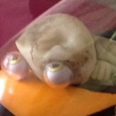
John Rickett 102 Posted February 29 Share Posted February 29 There had been a bit of damage to the extreme nose so a piece of balsa was grafted in and covered with glass cloth. After cutting back it blends in quite nicely, the trick will be whether the paint can be blended in as well. With the weather still not being suitable for painting outside, attention was paid to making a plug for the rocker covers. As well as the original ones in the kit being damaged, a bit of internet browsing showed that they were not a very good rendition of the Hispano Suiza direct-drive engine. Its possible that the bulges at either end were fairings, in which case they should be the same colour as the fuselage with only the straight centre part being black. I decided that as most SE5s didn’t have the fairings, the rockers should be less protruding and only showing a small bulge at the rear end, which I imagine is the valve timing gear housing. The plug was made from a couple of lengths of ½” balsa with a piece of 1/8” liteply at either end to form the shape, then a scrap piece of balsa both ends to allow a bit of a curve. The plug was then mounted on a board, standing proud by ½”, and covered firstly in two layers of 25gm cloth to better follow the curves, then one layer of 50gm cloth. After curing the surface was cut back, initially with 180 grade wet & dry then 240 grade. That gets a surface finish which is good enough for the subsequent coats of release wax. The next decision was whether to make a mould or simply to cast on the outside of the plug. Casting on the outside would be simpler but could lead to damage in trying to separate the parts and would also mean more rubbing down. I decided that, while a bit longer process, it was be safer to make a mould. 6 coats of Meguiar’s release wax were applied before mounting a parting board, cut from cheap 8mm B&Q ply, positioned along the centre line of the plug. The face was covered with parcel tape, the gap filled with decorator’s caulk and a further couple of coats of release wax to ensure that once the first layer of fibreglass was laid up, nothing was going to stick – always a trepid period. Here the first half has been laid up, it will be left for 24 hours to cure before putting those coats of release wax to the test! The reason for making a flange at the bottom is so that the mould can screwed to the board later and retain its shape and position while the second half is laid up. 2 Quote Link to comment Share on other sites More sharing options...
John Rickett 102 Posted March 1 Share Posted March 1 (edited) Excitedly watching the resin cure, I decided that the mould wouldn’t be rigid enough with the few layers of 50 and 100 gm cloth applied, so added two 200gm layers. The right decision I think as after 24 hours the mould popped off the plug fairly easily without distorting and feels sufficiently rigid to be useable. Hot glue was used to fix the parting board supports to the base board; I find hot glue quite good for this sort of application as it holds joints together - just, so is easy to break away afterwards. I’d also recommend decorator’s caulk as the medium for gap filling between the plug and parting board. I’ve tried both Plasticine and Playdough in the past but neither are as effective as decorator’s caulk. Its resilient enough to withstand the laying up process but can be easily removed afterwards by a simple rub with a thumb and leaves no residue. The excess fibreglass was cleared away using a Permagrit rotary cutter in a rather ancient Minicraft hand-held drill – it will be a sad day when this drill packs up, I can’t guess how many models this has helped to construct. The cleaned up first mould half refitted and gap filled with decorator's caulk. A few more coats of release wax and then the other half can be laid up. Edited March 1 by John Rickett 102 Quote Link to comment Share on other sites More sharing options...
John Rickett 102 Posted March 2 Share Posted March 2 After another 24 hours, the second half of the cowl has been released from the plug and the excess from the edges removed. The next job is to bolt the two pieces together and start the waxing process again in preparation for the first rocker cover lay-up. 2 Quote Link to comment Share on other sites More sharing options...
Andy Stephenson Posted March 3 Share Posted March 3 Do you use PVA as well as wax or just wax on its own. I've heard that hairspray is a good substitute for PVA*. *PVA=poly vinyl alcohol, not poly vinyl acetate. Quote Link to comment Share on other sites More sharing options...
John Rickett 102 Posted March 3 Share Posted March 3 Andy, I just use wax, this one. I've tried a few products, including PVA, but none seem as good as this stuff. The instructions on the tin say to apply 6 coats but I've found the more the merrier and at least 8. For subsequent lay-ups 5 or 6 are sufficient. A tin will last for years if the lid is replaced tightly. Quote Link to comment Share on other sites More sharing options...
Andy Stephenson Posted March 3 Share Posted March 3 Is it applied with a brush? Quote Link to comment Share on other sites More sharing options...
John Rickett 102 Posted March 3 Share Posted March 3 (edited) Apply it just as you would for wax furniture or car polish. I use an old bit of towel which remains in the tin. Its absolutely saturated with wax by now but that's probably an advantage. Apply liberally, let it dry for a few minutes then buff to a shine..........then repeat and repeat! Edited March 3 by John Rickett 102 2 Quote Link to comment Share on other sites More sharing options...
John Rickett 102 Posted March 4 Share Posted March 4 (edited) Adhering to the regime of 8 coats of release wax, which really didn’t take too long, the halves were bolted together and given one last wax along the join, then laying up started. Two layers of 25gm cloth were applied, this was to ensure that the cloth followed the tight curves. After that 2 layers of 50gm cloth were applied and finally one layer of 80gm. The resin had cured sufficiently after 12 hours to undo the bolts and pop out the casting. It needs to fully cure before it can be trimmed, but the mould is free again to make the second casting. Edited March 4 by John Rickett 102 1 Quote Link to comment Share on other sites More sharing options...

Recommended Posts
Join the conversation
You can post now and register later. If you have an account, sign in now to post with your account.
Note: Your post will require moderator approval before it will be visible.