J D 8 Posted July 6, 2021 Author Share Posted July 6, 2021 The little wooden hammer in the pic above is my oldest possession/tool, having had it since I was three years old. It came in a toy set called a TIP TAP something or other. A bit like Fuzzy Felt [ remember that ] where you made up pictures from felt shapes you stuck to a board. Only wit the TIP TAP you fitted coloured wooden shapes to a [soft ] board with actual nails, You won' see that with todays toys. Quote Link to comment Share on other sites More sharing options...
J D 8 Posted May 8, 2023 Author Share Posted May 8, 2023 It is strange is it not, that we modelers start on a build or other project and then for no particular reason it just comes to a stop and something else is started or continued. has been this way with my Bristol for nearly two years. Still underway again. A clean up of the engine reveled it is not an ASP 80 as originally though but a SC91 [ this could be good as its a bit of a bruit ] I have had it running. As can be seen in pic tank has been moved forward to a better position and engine is running well. Question is the prop fitted is a 12x6 where as Enya 90 in my Major Mannock is a 14inch. Any one with experience of the SC91 and what it is like? Quote Link to comment Share on other sites More sharing options...
GrumpyGnome Posted May 8, 2023 Share Posted May 8, 2023 I have an SC91 in my Valiant. Runs nicely on a 14x7, bags of power, quite smooth, throttlrs nicely. I have an on board glow as the engine is inverted and I didn't want to hack around moving the tank - very reliable, starts easily. 1 Quote Link to comment Share on other sites More sharing options...
Frank Skilbeck Posted May 8, 2023 Share Posted May 8, 2023 I have an ASP91 (same stable as SC) in my Jungmeister, runs great on a 14 x 6. Very reliable and runs great but likes 5-10% nitro. We have one of these Flair F2B which was built by a deceased club member many years ago, it has a warp in one of the wings and has been through several hands but as yet has not been sorted. I suspect this one has a 2 stroke engine, probably an Irvine, in it as that's what Hugh used to fit in all his models. I'll have to find out where abouts it is on the pass the parcel. Quote Link to comment Share on other sites More sharing options...
Robert Parker Posted May 8, 2023 Share Posted May 8, 2023 Hi J D 8, I too can vouch for the SC91, mine has been in my Tiger Moth for years. Mounted in inverted I had a few problems at first few flight always dead stick. Once I fitted an on board glow never any issues, starts easily even after a year or two without being run. Regards Robert Quote Link to comment Share on other sites More sharing options...
Geoff S Posted May 8, 2023 Share Posted May 8, 2023 I would have thought a 12x6 on a 91 four stroke a bit small. That's the size I ran on the OS52 Surpass that I had on my Flair SE5a before I electrified it. The 14x6 suggested by Grumpy Gnome would seem to be nearer the mark. Quote Link to comment Share on other sites More sharing options...
J D 8 Posted May 8, 2023 Author Share Posted May 8, 2023 14x6/7 it will be then, makes more sense. Thanks all. Quote Link to comment Share on other sites More sharing options...
Paul james 8 Posted July 12, 2023 Share Posted July 12, 2023 I have a Flair Bristol F2b that I bought part built. My current job is fitting the interplane struts. With the top wing attached at the cabane struts the rear wooden struts fitted well at the length suggested on the plan. I'm now looking to make the front struts but the leading edge of the top wing seems too low. Looking from the end the lower wing seems to have around the incidence I would expect (governed by all the meccano hanging off the bottom of the fuselage) but the top wing seems to have a fair bit less incidence, which would require the front struts to be a fair bit shorter than the plan. When I mention plans I don't have all of them, just the part that has been cut out and glued to the sample struts by the previous owner. Before I go any further is anyone out there able to advise on some reference dimensions from their plans or finished model? Perhaps I need to extend the front cabane struts a bit to lift the leading edge of the top wing and then make up the front 4 struts to suit? I'd be interested to hear what the dimensions you might have for the height from the centre of the leading edges of the wings and the same for the trailing edges. Any help would be greatly appreciated. I'd like to get the model ready to fly at the Flair meeting on 6th August if possible. Quote Link to comment Share on other sites More sharing options...
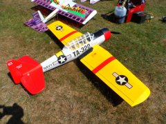
J D 8 Posted July 12, 2023 Author Share Posted July 12, 2023 Hi Paul, The on going fix up of my Bristol is on the back burner again this time due to house re decorating. However this model has flown before.[ not by me] The usual set up for this type of aircraft is to have the top/front wing set 2/3degrees greater incidence than the lower wing so as the stall approaches it is the top wing that stalls first dropping the nose and increasing flying speed to recover. The lower wing will keep flying unless the pilot provokes it to a full stall. Powerful aerobatic types tend to have both wings set the same at 0 degrees, after all they spend a lot of time upside down Pic's of mine. Bottom of lower wing level with table and bottom of top wing is sloping slightly up towards the leading edge I guess this gives about 2 degrees greater than the lower wing. Hope this helps. John. Quote Link to comment Share on other sites More sharing options...
Andy J Posted July 18, 2023 Share Posted July 18, 2023 Well its obviously the season for Bristol F2B's as I have just acquired one thanks to Ebay. Interested in any mods that will make rigging easier. My airframe came fully rigged and it took a good 30mins to undue the 6bA strut joints apart using a flat bladed screw driver. First job therefore will be to replace all these fixings with 6BA cap bolts as sure that will make the job far easier. That will be also be a mod I will also do on my Puppeteer as that is a pain to rig. When I get the laser 75 installed the next job will be to modify the throttle servo as the current position was far from suitable. Tank is well back, but looks ok in height for the laser carb, so will keep its current position. Given the undercarriage rear fixings have to be removed to allow the lower wing to come off, thinking the 2 plastic retaining clips secured by self tappers could be replaced with machine screws fitted into screwed standoffs let into the wing. Quote Link to comment Share on other sites More sharing options...
Paul De Tourtoulon Posted July 18, 2023 Share Posted July 18, 2023 Getting there, I use 3 mm cruciform screws on my bi planes and a 10€ battery screwdriver to put them together, now down to 6 minutes putting them together. Quote Link to comment Share on other sites More sharing options...
J D 8 Posted July 18, 2023 Author Share Posted July 18, 2023 As can be seen in pics above mine was modified by original builder to have separate center sections and wings. The upper and lower wings remain together by their interplane struts as a cell and slide onto carbon rods fed through the center sections. Connect a servo plug each side and a single screw for each wing retains the lot. Don't know how much weight this added or what effect but it goes together in less than five mins. Quote Link to comment Share on other sites More sharing options...
Paul De Tourtoulon Posted July 18, 2023 Share Posted July 18, 2023 I did my Tiger moth this way, just slot it in and a plastic screw in each wing. Quote Link to comment Share on other sites More sharing options...
J D 8 Posted July 18, 2023 Author Share Posted July 18, 2023 The Bristol does not even need a support plate as it is a four bay wing with four interplane struts per side. Quote Link to comment Share on other sites More sharing options...
Andy J Posted July 18, 2023 Share Posted July 18, 2023 My wings are one piece so should only require 22 screws fitted as will leave the struts connected to the top wing. (well at least that's the plan.) A small electric screw driver would be a good idea Paul. A Sonic type would be even better if I can persuade Doctor Who to give me his. JD.... have you considered a correct CoG position yet? Quote Link to comment Share on other sites More sharing options...
J D 8 Posted July 18, 2023 Author Share Posted July 18, 2023 Hi Andy I have been checking on the CG position. Mine came with the box and the building instruction sheets but not the plan. However it says on the sheet " The completed model, with empty fuel tank MUST balance 2 or 3 degrees nose down when supported under the upper center section at point 130mm back from the leading edge". Mine balance's some 10 to 20mm further forward, need to check on this some more. There is a load of lead in the lower front cowling to achieve this. Another thing to consider is the elevator movement, they are large and a long way back and so should be quite powerful and not need huge movement. No info on how much. I do not usually bother with rates [they are in my fingers] but with this one I may, at least to start with. Cheers, John. Quote Link to comment Share on other sites More sharing options...
Andy J Posted July 19, 2023 Share Posted July 19, 2023 On 12/07/2023 at 14:04, Paul james 8 said: II'm now looking to make the front struts but the leading edge of the top wing seems too low. Looking from the end the lower wing seems to have around the incidence I would expect (governed by all the meccano hanging off the bottom of the fuselage) but the top wing seems to have a fair bit less incidence, which would require the front struts to be a fair bit shorter than the plan. When I mention plans I don't have all of them, just the part that has been cut out and glued to the sample struts by the previous owner. Before I go any further is anyone out there able to advise on some reference dimensions from their plans or finished model? Paul, would you like me to measure my struts given both my wings used the standard construction method? Quote Link to comment Share on other sites More sharing options...
Andy J Posted July 25, 2023 Share Posted July 25, 2023 Did a rough check on the CoG this morning and was pleased to find that the position was very close to the 130mm back from the leading edge. Did add a little lead though just to ensure it is nose heavy. Whilst the cap screws do make the job of rigging easier the down side is that I laid in several ants nest that had popped up on the lawn. New 13x6 prop from PropGuy does look good on the model. Had to destroy the RAF roundels on the lower wing to get access to the servo leads which did not provide a reliable connection. Now looking for a cheap source but as the Type A come in at £18 approx for a 250mm diam version wonder if paint would be a cheaper option. Quote Link to comment Share on other sites More sharing options...
Andy J Posted August 8, 2023 Share Posted August 8, 2023 Getting a lot closer now to getting the airframe in a condition it can be flown. Cap screws makes rigging a lot easier and will be replicating this approach on my Puppeteer. Action man figure also added. Some work needs to be done to the fin as it has the leans and also to the undercarriage which has a similar problem. 2 Quote Link to comment Share on other sites More sharing options...
RottenRow Posted August 8, 2023 Share Posted August 8, 2023 Andy, It might just be a camera angle thing, but your port upper wing looks rather twisted, with wash-in. It might be worth you checking that out before your first flight, just to be on the safe side. Brian. Quote Link to comment Share on other sites More sharing options...
J D 8 Posted August 8, 2023 Author Share Posted August 8, 2023 Solid UC or bungy suspension? Quote Link to comment Share on other sites More sharing options...
Andy J Posted August 8, 2023 Share Posted August 8, 2023 (edited) Think the wing is indeed twisted but don't think I can correct that. Certainly the model was sitting lob sided as the undercarriage fixings was not tightened down. Nor does the rear section piano wire sit snugly into the recess on the underside of the lower wing so will have to adjust how the front legs interface with the leading edge to get it to bend down more. Undercarriage is a solid construction currently JD. Will see how it performs once I have is fitting correctly. One mod I did do was to let in some M3 machined bushes into the lower wing since the rear fixing of the undercarriage saddle clamps have to be removed each time the model is rigged. Puppeteer is the same so will do a similar mod to that airframe. Bushes I used are obtainable from here. You do need to run an M3 tap through them as the M3 tapping is applied from both ends. Unsure how I can also correct the lob sided fin as pictured as I don't know if it uses a simple flat edge contact to the fuselage or somehow it is let in to the structure or has a rear stern post which protrudes into the fuselage. Any chance anyone has a copy of the plan for that area? Could apply some torsion to the tail rigging wires to correct the lean to one side but suspect that will only cause the tail to warp. Edited August 8, 2023 by Andy J Quote Link to comment Share on other sites More sharing options...
Andy J Posted August 8, 2023 Share Posted August 8, 2023 Found this old thread which seems to indicate that the fin just sits on a flat infill built between the fuselage stringers at the rear. So will see if I can slide a scalpel blade in to break the glue bond. Quote Link to comment Share on other sites More sharing options...
jeff2wings Posted August 8, 2023 Share Posted August 8, 2023 Just re -tension the wires to hold it straight, you know, like they would have done on the full size a/c ? And if the lower wing is flat and the upper has a twist then you need to adjust the strut length Quote Link to comment Share on other sites More sharing options...
J D 8 Posted August 8, 2023 Author Share Posted August 8, 2023 Hi Andy, I do not have the plan as such but do have the build sheets. They show the top and bottom fin's are just glued to decking between the longhorns. As above just re tension wires to correct. Looking at your pic are the wires fixed at the horizontal tail or do they just pass through tubes? John. Quote Link to comment Share on other sites More sharing options...

Recommended Posts
Join the conversation
You can post now and register later. If you have an account, sign in now to post with your account.
Note: Your post will require moderator approval before it will be visible.