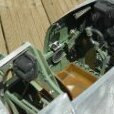
david tilbury Posted February 22, 2023 Author Share Posted February 22, 2023 Hi Jon......been there before.....:-( Gun cover fits well.....now i'm happy with the shape and overall look i'll remove the underside wood/filler part ready to be made into the required hatch... Also made a start on the mid fuz hatch which will give access to the elevator servo....same as the Sist models i have.... Quote Link to comment Share on other sites More sharing options...
david tilbury Posted February 23, 2023 Author Share Posted February 23, 2023 (edited) I like the idea of just removing 200g/7oz of weight from the fuselage with a hammer and chisel a bit crude i know but seemed the quickest way......plus i still have about 3mm offset to remove and make good so that the cover fits flush or just proud..... Sheeted part of the wings and added the fairing base/fairing formers......front leading edge blocks on the fuz......and made good the hatch location on the left side of the fuz.....needs a door at some point or small screws to hold in place Before sheeting the wings i added 6mm of light ply to the top shape of the wing joining rib, this will give me a harder edge to use as the butt joint between the center section and outer panels rather than balsa. Cheers Edited February 23, 2023 by david tilbury 2 Quote Link to comment Share on other sites More sharing options...
Martian Posted February 23, 2023 Share Posted February 23, 2023 Smashing stuff David 😉 Quote Link to comment Share on other sites More sharing options...
david tilbury Posted February 24, 2023 Author Share Posted February 24, 2023 (edited) Thanks Martian.....:-) Spent some time today facing off the two side of the front wing join, slight change to the plan.....used some 0.8mm ply on the fuz side and 2mm light ply on the wing, again i have this hang up about glassing balsa edges and making them look good.....now both will look really crisp once painted, also the gap between is 0.8mm.....just used some extra ply pieces as a stand off when i was glusing the sheet on as shown.. The curve applied to the underside of the ribs is paying off as well, it's looking like the 1/48 plastic kit i have.....which is a great reference. To achieve the flush fitting of the balsa i made a balsa offset with a step of 1/8 all around the light ply.... the wing comes off easy which is good news.. Edited February 24, 2023 by david tilbury Quote Link to comment Share on other sites More sharing options...
david tilbury Posted February 25, 2023 Author Share Posted February 25, 2023 (edited) Facing off the fuz edge with 2mm light ply this morning.....this isn't vertical it's at an angle, the wing face will butt up against this Edited February 25, 2023 by david tilbury Quote Link to comment Share on other sites More sharing options...
Nick Somerville Posted February 26, 2023 Share Posted February 26, 2023 Nest solution and material choice for the high wear wing mount area. That’s going to be very satisfying when you come to assemble at the field. The greater the span the harder it is to be precise when mounting. Quote Link to comment Share on other sites More sharing options...
david tilbury Posted February 27, 2023 Author Share Posted February 27, 2023 Hi Nick, agree....:-)......cheers Seat almost finished.......spent sometime sanding down the underside of the wing as well today.... 1 Quote Link to comment Share on other sites More sharing options...
david tilbury Posted March 3, 2023 Author Share Posted March 3, 2023 Before finishing the planking on the sides i need to complete the rudder/elevator linkage/movement, so finished the rudder today, inserted scale hinge points.. once i'm happy with everything i'll add solatex to the surfaces Still pleased with the overall weight with the tail surfaces attached Also printed he seat bucket...:-) 4 Quote Link to comment Share on other sites More sharing options...
david tilbury Posted March 4, 2023 Author Share Posted March 4, 2023 (edited) Seat almost finished......some small details to add plus the harness strap fixings.....and the rear seat location points... Interesting to see the difference between the correct scale and the supposed 1/5 scale from Aeroteam which i bought some years ago......have to replace the 2 i have in my A8 and D9 as well.. Edited March 4, 2023 by david tilbury 1 Quote Link to comment Share on other sites More sharing options...
Jon H Posted March 4, 2023 Share Posted March 4, 2023 I hate your posts Dave. Every time i check your updates its always 'oh yea while bored i did a 3d CAD model of the entire known universe and 3d printed every atom at 1/4 scale'. Whats next? alternate dimensions? Awesome work as usual though, but i double hate you as i now need to buy a 3d printer to try and up my custom parts game but i have no space for one 😞 For now i will have to be satisfied with cutting Spitfires in half and gluing them back together at a different angle. 1 Quote Link to comment Share on other sites More sharing options...
dave parnham Posted March 5, 2023 Share Posted March 5, 2023 He seemed to me to be the perfect gentleman when i drove to his house and brought the DR1 kit off him......perhaps a little disappointed i didnt get to see his man cave. Very controversial to say and tongue firmly in cheek Could this 3D printing Lark not be classed as Cheating?😀 I mean us mortals have to use wood and metal and glue and make things look half as good as daves Printed parts. Seriously though Dave Tilbury Keep posting this Brilliant build i also watch Richard Craps builds on the other channel. Quote Link to comment Share on other sites More sharing options...
Jon H Posted March 5, 2023 Share Posted March 5, 2023 50 minutes ago, dave parnham said: Could this 3D printing Lark not be classed as Cheating? gotta learn to use it though 😉 Quote Link to comment Share on other sites More sharing options...
david tilbury Posted March 6, 2023 Author Share Posted March 6, 2023 Hi Jon, Dave, Thanks for your comments, the use of computers/printers/3D CAD is a big subject to talk about within our hobby too big to chat about on my thread, it has come up several times within the BMFA scale technical committee as a subject to whether it's a good or a bad thing, but i'm afraid it's here to stay.......cheating ......never been called a cheat.....no offence taken Dave, not that sort of person. Yes Jon you do have to learn it like any other skill, it's not easy very frustrating at times, you could say the same for bashing balsa and metal which i still do and enjoy just as much as sitting in front of a computer and designing something in 3D CAD. I need to get on with some changes/mods to the Sierra tailwheel unit making it more scale, so some metal bashing today and turning in model lab board......so i won't go on talking about the above. All the best Dave Quote Link to comment Share on other sites More sharing options...
Jon H Posted March 6, 2023 Share Posted March 6, 2023 I think the cheating comment was aimed at me. I caused upset on another thread by suggesting some would rather cheat their way round a problem rather than take the time to learn a skill to get around the same problem. The over use of technical aids was part of the debate as they can be used to mask lacklustre flying skills. However using these technical tools to create something is not cheating. You have to do the research, learn the tools, use the tools to create the models etc so where is the problem? 1 Quote Link to comment Share on other sites More sharing options...
david tilbury Posted March 6, 2023 Author Share Posted March 6, 2023 (edited) Making good progress on the rear end, spent some time today adding some details to the Sierra tailwheel unit, this is semi scale so the final look will be a compromise, on the new S8 i will make from scratch so in keeping with the full size. First was to make the tyre and hubs, been making these for some years and supplying Sierra Giant Scale with 1:5....1:4.5 and 1:4 scale as they are foam, they are very light. The main changes to the unit is reshaping the yolk with files, adding a fillet radius at the top of the yolk with filler.....adding new axle ends, the screw that holds the axle in place has been replaced and the head diameter ground down, this now fits inside the new axle end. Some round shaped model lab board parts.....also ordered some Milliput epoxy filler for the welds which need adding......hopefully the final look will be better than the standard brought tailwheel assembly.. Edited March 6, 2023 by david tilbury 1 Quote Link to comment Share on other sites More sharing options...
dave parnham Posted March 6, 2023 Share Posted March 6, 2023 (edited) 3 hours ago, Jon - Laser Engines said: I think the cheating comment was aimed at me. No john not aimed at you...... The 3d printing in general. Whilst i admire the building going on, and we must not fill Daves Blog up with my words,i actually like whats being achieved here and if i could would probably do the same. John your spitfire build is also to be admired, and you may well choose to add a 3d printed cockpit. i just remember when we all struggled with a ply dashboard and cut holes out and used washers or ply rings for bezels etc. Modelling has clearly moved on for the better i guess. Edited March 6, 2023 by dave parnham Quote Link to comment Share on other sites More sharing options...
Jon H Posted March 6, 2023 Share Posted March 6, 2023 5 hours ago, dave parnham said: No john not aimed at you My mistake 👍 Quote Link to comment Share on other sites More sharing options...
Paul De Tourtoulon Posted March 7, 2023 Share Posted March 7, 2023 Here we go ( I hope not 🤢) 3 D printing is a new addition to modelling, advancing it to a higher level, a club member will spend hours drawing a 3D plan out to 'save' (🤣) 1 hour of balsa cutting and gluing together, or should we go back to rubber powered free flight ?. Quote Link to comment Share on other sites More sharing options...
GrumpyGnome Posted March 7, 2023 Share Posted March 7, 2023 I don't think anything that enhances your building/flying pleasure is cheating. And pretty much everything needs you to learn or improve new skills. Great woodwork and use of modern technology on show! 2 Quote Link to comment Share on other sites More sharing options...
leccyflyer Posted March 7, 2023 Share Posted March 7, 2023 2 hours ago, Paul De Tourtoulon said: Here we go ( I hope not 🤢) 3 D printing is a new addition to modelling, advancing it to a higher level, a club member will spend hours drawing a 3D plan out to 'save' (🤣) 1 hour of balsa cutting and gluing together, or should we go back to rubber powered free flight ?. I did see an example a few days ago where a laser cutter had produced it's first set of parts which were two rectangular pieces of 1/16th sheet, a few inches square, which could have been cut in seconds with a sharp knife and a metal straight edge. However there any many things which can be easily produced with a 3D printer which would be beyond the skill levels of all but the most proficient scale modellers, where someone else has done the design work. My own main aim in starting 3D printing was the capability of producing perfectly scaled and historically accurate pilot busts, just the right size for the models that I fly. There isn't a hope in hell that I could develop the sculpting skills to produce these from balsa, or any other material for that matter, With a 3D print file and a 3D printer i can have nice scale pilots in any scale I like, within reason. I certainly don't consider that to be cheating, the notion is ridiculous. Quote Link to comment Share on other sites More sharing options...
Jon H Posted March 7, 2023 Share Posted March 7, 2023 21 minutes ago, leccyflyer said: I certainly don't consider that to be cheating, the notion is ridiculous. I completely agree. I am not sure why there is so much excitement about it! I would dearly love to be able to make more little scale bits for my models and its another skill to learn. Quote Link to comment Share on other sites More sharing options...
Paul De Tourtoulon Posted March 7, 2023 Share Posted March 7, 2023 It's a shame no one has the use of a scanner to re produce 'your' head on a bust I have a friend in Montpellier who had one made, it was brilliant. Quote Link to comment Share on other sites More sharing options...
Martin Harris - Moderator Posted March 7, 2023 Share Posted March 7, 2023 Posts relating to the comment above split off into new thread 1 Quote Link to comment Share on other sites More sharing options...
david tilbury Posted March 8, 2023 Author Share Posted March 8, 2023 (edited) Thanks Martin.....:-) Closed the rear fuz today, planked balsa......found the large curve up to the rear of the canopy was R1100.00 so made a sanding block to suit from blue foam.... Also enclosed the main part of the side below the cockpit......cut some ali angle to make up the wing retainer mounts, these will be drilled to suit M3 cap head screws.....as the wing tube is quite forward in the wing i think it only needs the one fixing point once together..... Another point is the canopy i have needs to be wider at the rear to fit the current ply plate which i thinned yesterday a tad as it was looking much wider, so have to make a pattern of just the rear section, was thinking how i was going to make the frame here anyway....so that answers my question.... The round circle on the fin is extra balsa as it somehow was sucked in, looking at the full size it's much straighter.....much better now Cheers Edited March 8, 2023 by david tilbury Quote Link to comment Share on other sites More sharing options...
david tilbury Posted March 9, 2023 Author Share Posted March 9, 2023 (edited) Some more CAD work today, the supercharger.......the plan is once i have built the CAD which will be quite a bit of surfacing which doesn't come easy as you CAD users know, i'll then decide on how to make it......first will be print a skin, if the skin weight is ok then i might use it otherwise a glass mold might be an option.....anyway CAD first. The starting point is the photos i have as all the drawings i've seen don't tally with the photos, they are all different in some way.......below the images i'll use. Be back later with some updates.....also hopefully today i might get my Milliput filler, so more on the tailwheel, weld lines etc. Edited March 9, 2023 by david tilbury Quote Link to comment Share on other sites More sharing options...

Recommended Posts
Join the conversation
You can post now and register later. If you have an account, sign in now to post with your account.
Note: Your post will require moderator approval before it will be visible.