Leaderboard


Popular Content
Showing content with the highest reputation on 05/04/22 in all areas
-
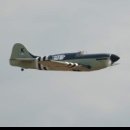
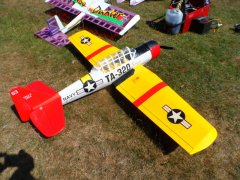
Defiant landing, slower than I expected with its 13lb weight5 points
-
So while the washout jig strip positioning and general first part of the wing construction is fresh in mind I have made a start on the other side. The first wing is propped up in place with the root at zero incidence again and a measurement taken from board to tip and this checked against the relevant drawing on the plan. Just a little tweaking of supports and everything sat in place ready to build off.3 points
-
Ailerons liberated and hinged. That's all the hinges done. A bit of sheeting on the bottom of the fuselage to do then it's shape and sand ready for covering. Steve3 points
-
Defiant flypast...3 points
-
The turret doing its thing. It has to whizz about like a demented Dalek or you cannot see it in flight!3 points
-
It’s official, this is the last bit of the fuselage I can sheet until the retract turns up ? However, I’m really enjoying this. Some of the curves are a nightmare to get right but I’m sure that these curves will look great once done and sanded in. The back end of the wing was very tough. I’ve got a few more small jobs on this before I have to pull my finger out and change the workshop around so I can start on the stab at some point.2 points
-
With painting complete its time to get on with the engines, tanks and undercarriage installation. The trousers completely enclose the inner engines so to allow for glow connection, a mini jack-socket is located just behind the cowl. With the cowl in place the male connector can access the female jack-socket. The one below is for the an outer engine, these are a bit more accessible so only needs a bracket to hold similar jack-sockets. The bracket then fits almost flush with the bottom of the cowl. In each case the glow plug connector part is a few turns of spiral wire with the lead soldered on and covering with heat shrink to take the load away from the solder joint. I used to use the old nylon wire curtain rods as they were a good fit on the plug posts of a few years ago. With a standardisation for all my Lasers to using OS 4 stroke plugs, which have a wider than normal post, the wire that is used for a certain type of stationery file folder, is a pretty good fit. Buy a couple of these if you find them in a stationery shop and you'll be set up for years! With just one turn snapped over the plug, they are not going to let go very quickly.2 points
-
We are running a BMFA In te Air Tonight session on the Centenary and record attempt. Tuesday 12th April at 7pm. See https://itat.bmfa.uk/12-04-2022 to register to join in.2 points
-
I have a couple of old models with nylon covering. The starboard lower wing's paint finish of my old DB Major Mannock was pretty well ruined so after cleaning off the worst with acetone and powder carefull sanding with wet and dry removed the remaining bits and wing was repainted My 1970's built Bleriot had a similar problem on the underside of port wing, similar treatment cleaned it up and it was then left natural fabric. Pic shows work in progress.2 points
-
Which particular screws on the engine are you referring to? The cylinder head screws are 4-40 UNC x 1/2" long. The crankcase screws are 4-40 UNC x 3/8" long. The exhaust fixing screws are 6-32 UNC x 1/2" long. Best source I know for these is Modelfixings.2 points
-
Building finished - just got to do fitting out and add the electrical bits....2 points
-
Only a little bit of work tonight, dry fitted the ruder closed loop arm and cut out slots for the clevises. Dry fitted to fuz again and sanded more. Cut and added ribs to stop warping. This will now be put to one side for a while as I have another area I can sheet whilst waiting for the retract.2 points
-
Yes, I built it from the Sarik short kit, been flying it for a year, it flies very very well! Mine was featured in the January RCM&E. I use 6S 5000 through a Ripmax Quantum 61, I fly until 70% capacity (3500mAh) is used and am getting 10-12 minutes of flying, mostly very low long passes at which it excels due to very good stability. I made a working turret which uses 4 channels and is controlled by transmitter sequencers. I just switch it on or off. The fuselage fairing drops out of the way, the turret rotates back and forth nearly 180 degrees, the guns go up and down, and the muzzles flash. That and the tail heavy design or wood meant a lot of lead up front and it comes to a whopping 13lbs. Yet it gets airborne off grass by the time I get to 3/4 throttle, and it lands quite gently. Full flap is like running into a brick wall so be ready with more power and nose down. Lovely flying model, I haven't a bad word to say about its handling.2 points
-
I built the Boulton Paul Defiant (Chris Gold plan ) but not flown it yet . The model is electric powered with 6s lipos and retracts and flaps. Has anyone built this model and flown it yet1 point
-
I have had the accompanying article since it was published in the 1954 Aeromodeller Annual (when I was a boy!). It's a very interesting account by the author of the article, Mr. W. Ball, relating his post war development of his designs for rocket and pulse jet engines, (large) delta radio controlled aircraft, and- axial jet engines! This was a good 30 years before the success of the UK team led by Jerry Jackman, in making that first micro-turbojet flight, in 1983. Interestingly, towards the end of the entertaining article, as he relates, tragically, the results of 10 years of work were destroyed in the Great Floods of January 1953 (I remember them well- who says that Global Warming is new??) Now- was this a man before his time? There's a cutaway illustration of Ball's jet engine- I am not familiar with jet engine design, but some of you may know how practical the design was- or not? There is no real way of telling. Unless some of you may have more information?1 point
-
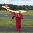
I will put this here because it is (or was) a Peter Miller Ballerina but made of Depron right at the end of the 2016 mass build. Although built to the free plane outline it was unusual, apart from being ridiculously light, in that it had retractable U/C including the tail wheel. After hanging on the wall for nearly 2 years I decided to fly it only to discover the retracts had failed. One leg simply did not move and the other went up and down a couple of times and then failed extended. Obviously with 'one up & one down' it could not be flown. To make matter worse I fly from a rather rough grass field so most of its flights were hand launch and belly land with the U/C just retracted for show! The retracts were cheap HK units and even if I wanted to replace them they are no longer available so I made the decision to make it hand launch and belly land only! This would also save a bit of weight, not that an all Depron Ballerina really needs it. Some 'surgery'. The ribs ahead of the spar replaced with 'printed' ones. Hopefully when the skin (2 mm Depron!) goes on you won't be able to see the join.1 point
-
Last job of the day was to select the three pieces of C/F coated wood that forms the ESC platform. I used 5 minute epoxy to complete this job. There were pre-cut slots to accommodate the frame which was helpful. That's it for today. Next up some work on the operating surfaces.1 point
-
The cowl was test fitted and checked. Seems near enough.1 point
-
Just been reading through, Garry and really impressed with all of your work and progress. Your photography is exemplary and with the descriptions reads like a comprehensive build manual along with all the bits normally missed out. Wish I could keep my space as tidy.1 point
-
Had a choice today, fit the first upper wing skin or make a second skin, second skin it was! Spent some time sanding any lumps and bumps, high spots etc on the wing structure so that the skins sit evenly with no stress points anywhere. Sanded the false leading edges down more to match the rib profiles, the actual leading edge stock in the kit is just wide enough to do the job. Secured the aileron servos (CA) and wiring, functionally checked the system. Fairly sure that I can fit the upper skins now (will have one last read of the instructions and glance at the plan). 1. Checking the leading edge strip after sanding down the false leading edges, strip is just taped on here for effect, will check this again before gluing the skins on, at the very worst I could cut new stock. 2. Checking that the aileron servos and extensions are good. 3. Wing ready for the upper skins (I hope!). Remembered to add the servo horn screws.1 point
-
I don't really do IC so am no expert, but suspect you would be better choosing a kit designed for IC - the front end would need quite a lot of mods to accomodate the engine and fuel lines. I suspect it would be easier to just start with a Cambrian kit if glow is your power choice. Also a 10 might be a bit marginal on power, a 15 (with around ~300W) is probably a better match.1 point
-
As above. Just a bit of aluminium from a drinks can for the same reason, it is 50 years old and wing is still covered with original tissue and many original patches as well as some newer ones. Tail was recovered with silver lightspan when radio was fitted some years ago.1 point
-
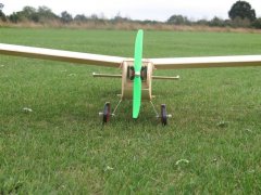
It's a trim tab, bend it upwards if the model persists in turning left! There's one on my old Junior 60 to compensate for a warped wing.1 point
-
Hi Nick and thanks ? The rudder hinges are a type of plastic which a bought from America CB associates I believe and were detailed on the plan. The pin is 3mm carbon rod and will be fixed in place at the bottom with epoxy. It’s only removed if I need to repair it so would be a case of just drilling out the lower hinge 5mm or so. I still haven’t decided covering material yet but the top of the rudder and bottom will be carved from foam to keep the weight down. The balsa post is quite heavy and it’s a ply former. I will seal the foam with epoxy to make it tougher.1 point
-
Packing the wing trailing edge a little at a time is a good way of getting the climb angle you want, less touchy than doing adjustments at the tail. The model design itself harks back to free flight days when thrust and wing adjustments were common I recon. My old free flight Matador [ now RC assist ] is throttle, rudder control with a small trim tab elevator on a switch. throwing the switch gives some down which enables the model to penetrate into wind when if you just opened the throttle it would only climb.1 point
-
Substantial build and great to follow along Craig. Can you elaborate on materials used for the rudder hinges please. From what I can see you have cut the hinges from carbon plate of some sort and then used a removable carbon rod to run through as a pivot. If the rudder is intended to be removed for transport how is the pivot rod held in place.1 point
-
I would think Profilm/Oracover.1 point
-
If only. I know you actually meant internal resistance increases and hence the C rating decreases but ... ? I find once IR goes above 10 milliohms/cell (or even before for some applications) the battery is toast. Lower than 5 milliohms/cell is better. Though I don't make big demands of my cells as I don't fly ducted fans and use the throttle in both directions.1 point
-
Can you not add some downthrust, or maybe pack up the TE of the wing a tad? Nothing wrong with throttle to elevator mixing per se, but if the tendency to climb under throttle is as pronounced as you say it would be better to reduce that substantially through a combination of thrustline and decalage, then fine tune with a mix.1 point
-
I tend to design my own: And for where transparent film is going to be used for the covering1 point
-
Second garden run, engine leaned out, @GrumpyGnome listen when I remove the glows, revs don’t drop like they did yesterday. This, imo, proves that on-board glows can cover up poor engine tuning.1 point
-
Filled in the gaps to add strength to the battery box. then trial assembly, just to check the fit. fine ? Steve1 point
-
Corners knocked off the balsa blocks and 'coffin' glued in. Steve1 point
-
Thanks, that is a useful read. It looks like it goes together well other than a few slightly odd choices of hardware, though I'm not sure converting a model with a structture like this to IC is the best of ideas - better to start with something designed for the purpose. Certainly mine (if I get one, most probably the Spit) would be electric powered.1 point
-
This is a current thread about one of the VMC kits. https://www.modelflying.co.uk/forums/index.php?/topic/49070-vintage-model-company-cub-4-channel-trainer/1 point


.thumb.jpg.77e29add7c1431e70c716c79b427fca9.jpg)