Leaderboard
Popular Content
Showing content with the highest reputation on 19/06/22 in all areas
-
If you put your model aeroplane on the ground where cars are parked (a car park) even for a moment, sooner or later you can expect it to be run over by a car. I think a motor insurance company would find someone making a claim for damage to personal property under these circumstances hilarious and reject any liability. People are expected to take reasonable care of their possessions. The club chairman should make clear the committee’s position that his behaviour is unacceptable and that he must put it down to experience and get over it, or move on. No if’s or buts.5 points
-
I popped up to the north Kent coast slope this morning, but the wind wasn’t as strong as predicted. Still, got an hour’s soaring in with the Quicksilver and very pleasant it was.3 points
-
@Dave Bran: The present UK (and EU) power levels were not set by "holding a wet finger in the air". They were set on the basis of "what is necessary to do the job, without causing issues to other users". As such, they have proven remarkably effective. As I stated, the 100mW ERP goes right back to the days of 27/35 MHz. Even at those frequencies it proved more than adequate. In the early days of experimenting with 459MHz, we played with ready made Tx modules that only output 10 mW, and never experienced any range issues. Unlike 35 MHz, which is pretty much for the exclusive use of RC aircraft, 2.4 GHz is a "shared" band. We have to live with other users. Spread spectrum goes a long way to mitigating the effects of this, along with the fact that most of those other users are low powered and urban - unlikely to cause issues at a flying site. The problem with using higher power levels is the risk of "deafening" other nearby users on lower power levels. Even spread spectrum can ultimately fall foul of this. OK, an increase to 200 mW may not make much difference, but it won't make much difference to range, either. And since range is already "out of sight" at 100mW, why bother? All it will do is increase the battery drain. Yes, there may be locations where higher power levels may be desirable. I'm thinking of areas where there are already high levels of RF "pollution", but such areas are probably not ones you would be flying in anyway. And of course, there are quite a few totally unregulated areas world-wide! BTW, there is a misconception that you *have* to use Listen-Before-Transmitting (LBT) on 2.4 GHz. You don't. But if you don't, you are limited to a Media Utilisation Factor of 10% - in over simplistic terms, an output of 10mW. Based on my experiences on 459 MHz, that would still provide adequate range for our purposes, though personally, I am far happier with the higher margin afforded by 100mW. I'm reminded of the old joke: "To a pessimist, the glass is half empty. To an optimist, its half full. To an engineer, the glass is twice as big as it needs to be!" 100mW is fine. We don't need any more, as demonstrated by the thousands of people flying with it without incident. -- Pete2 points
-
On the home straight now. As pure guesswork I set the elevators at 17 deg +/-, ailerons 16 deg +/- and because I like a lot of rudder authority I set at 30 deg +/-. No expo at the moment because I just want to see how early flights go. The only thing left to do is set the throttle stick calibration, but I do that at the field. All these starting points are up for change, as I am quite cautious to start with hence the modest EPA on the working surfaces. I did manage to use 2 channels for the elevators and 2 for the ailerons rather than a y-lead and this gives much more flexibility when setting up the working surfaces. The cockpit design is quite attractive and finishes her off well. So really now waiting for ideal conditions for the maiden .........2 points
-
With the laminated G10 and carbon fibre covers completed the retract cover portion was carefully fretted out and both the upper cover and retract access cover tidied up to provide as close a fit as possible. The wing skin could then be cut away and hardwood lugs added for the access cover. These were drilled, soaked in cyano and tapped 3mm for some suitable short mushroom topped allen bolts. The lower wheel cover portion overlaps by 4mm beneath the leg cover and will be attached to the leg close to the axle using the supplied Sierra clamps. There is 30mm of compression available in the oleo so behind the upper leg cover a short length of brass tube has been set and fixed with carbon tows in the lower part of vac formed parts supplied with the plan pack. Once both the upper and lower parts have been drilled for the three saddle clamps and accurately aligned, a length of piano wire will be fixed to the lower wheel cover to both support the top and support the top and guide it when compressed. In the last picture you can see the two upper saddle clamps marked and the rear of the parts with the inner dressings.1 point
-
Decibel (dB) is a logarithmic measure often used for sensitivity measurements - not only of RF signals, but noise measurements too. A dB on its own doesn't mean much, as it is a ratio - like a percentage - and has no real meaning until you say " a percentage of what?". IE: 50% on its own is pretty meaningless, but if you say 50% of two, then you immediately know it means "1". a dBm means that 1mW (1/1000th of a watt) is what it is measuring against. So, a figure of -10dBm means 1/10th of a mW, -20dBm means 100th of a mW, -30dBm a thousandth, and so on. Essentially those figures for the Jeti (rounding them to -100dBm) are saying that its limits of detection are 1/1(followed by 100 zeros) of a thousandth of a Watt. Pretty adequate, I would say! Remember that radio waves weaken in accordance with a square law. If you double the distance, you quarter the received signal strength. So if the ERP of the transmitter is 100mW - well, I leave it to the mathematicians amongst you to work out the theoretical range based on those figures! (Don't see why I should do all the work! ? ) Let's just say its more than adequate! -- Pete1 point
-
After another re-tune it was time to try out d=some formation flying with a leccy powered H9 'Jug' - what fun.1 point
-
Yesterday saw our flying filed play host to an F3a competition, it was cold and a bit wet! Today it was back to 'normal' flying, my P51 formation flying with a P471 point
-
Cheers John, I was probably overdoing it in the heat. Some light tinkering in the shed today. Started the wing root fairings. Faced one aileron and sanded its hinge face. 1. Parts needed for the wing root fairings, die-cut 2.5 mm balsa sheet, die-cut 0.4 mm ply seats and routed Liteply formers. 2. Checking the wing seat fit, pretty good, just slightly over length. 3. Checking with the wing fitted, again pretty good. 4. Protecting the wing with iron-on film backing to prevent sticking the fuselage to it accidentally. 5. The ply wing seats were glued to the inner fuselage frames only then the wing was fitted followed by 'Superphatic' applied with a paint brush to the outer join line. Added F6B Liteply former. 6. I glued the balsa parts together, adding one at a time, slightly leaned over so that they fitted into the undercut of the fuselage side. The vast majority of this wood will be carved and sanded off. 7. For interest I tackled this job on my Brian Taylor Spitfire not so long ago, it uses curved sheet mainly instead of block, not the easiest part of the build but then none of it is!! 8. Back to the Fw 190, the leading edge of the ailerons need to be sanded at an angle to allow down travel (they are top hinged with tape). I drew a pencil line for a guide. 9. I hinged it with masking tape to check the travel available, instructions say 1/2" or 12.5 mm total which doesn't seem a lot but there should be more than enough here. I need to sand back the aileron face at the tip as shown on the plan. 10. I faced the aileron inboard end with 1 mm ply after sanding the leading edge. I usually place a scrap of 1 mm ply in the gap on final assembly for clearance.1 point
-
Many years ago when I was attending a small gathering as a guest of a local club, a chap reversed his car into my model - the exhaust pipe went right through the leading edge sheeting, the entire tailplane was ripped out and the model was quite badly damaged. The model was the prototype of the Webbit - a sort of mini Wot-4 sports model, with which I was having great fun at the time. The chap was very apologetic, but I took it as just one of those things that happen, an unfortunate accident, nothing more than that. It did however have two outcomes. Firstly it gave a good story and a grand opportunity for a wee bit of gentle ribbing every time I saw the chap- who I'd never met before - which seemed to happen quite often after that. Gentler ribbing than I had to replace in repairing the model. Secondly the wee Webbit was a bit of a poster child for the sticky mess that small glow powered models end up like, when it comes to repairs and I resolved to convert her to electric power, after the onerous task of stripping off all the icky, sticky Solarfilm. The result was a nice clean throw in the car model, rather than throw under the car model, which gave several years of good service, before succumbing to pilot error in my first foray into 2.4Ghz module use. I've still got the wing ?1 point
-
The problem is between the two people involved in the incident. In what way is that "ruining the peaceful enjoyment of the hobby for the rest of the club" ? It's bad feelings between them not towards anyone else. It is not the club's problem. If the club simply does not get involved & lets them sort it out (or not) it will, in time, blow over. OTOH if the club kicks them out friends of both parties will probably feel aggrieved which will lead to a worse situation all round. Also talking about ejecting them from the club is no more than short sighted macho rhetoric which may not be as easy to put into effect as imagined. One positive thing the club can do is to look at the circumstances that led up to the accident & see what can be done to avoid a repetition.1 point
-
At Weston Park today both SLEC & Balsa Cabin had loads of balsa. I wasn't in the market for any so did not examine closely but there appeared to be plenty of all sizes.1 point
-
1 point
-
1 point
-
3 flights this lunchtime with the Ruckus. About 27c but windier than forecast. Runway is starting to took scorched already1 point
-
Agreed spudsy this is a flying field loss incident. If you allow me a little sarcasm, reading through The message could be: You can now be careless with your models and gear as the BMFA will pay out for it ! ! ! ! My belief is that modelling gear is expendable and can be lost in an instant. This wing was lost due to carelessness on somebody's part and is gone ! Careless owner left the part in harms way, then it was destroyed. How is the BMFA responsible? If the BMFA payed out on this, would the flood gates open as we cash in our less popular models under car wheels? It is just Wrong, a model lost is gone.1 point
-
All true, but I am sure the car driver is thinking about his excess payment for this and the premium next year if he claims. If I were him and I thought I had some degree of responsibility I'd just pay 50% out of pocket and move on, that is almost certainly going to be the best option unless it's a very, very expensive model. If I thought it was the other blokes fault for placing it in an area members can legitimately park but hidden from view, I'd probably refuse to pay as well - who places expensive models in car park spaces anyway?! The club should just stay neutral, tell the parties to sort it out amicably, and if not apply their constitution as written to discipline/suspend/eject the relevant members once due process has been followed. PS - Any threats of police or legal interventions are completely empty IMO; the former won't be remotely interested and the latter will cost far too much to be viable.1 point
-
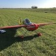
Maiden day for the 2022 mass built Mini Super, light winds and sunshine. This is the before picture and the after picture is the same ? Steve1 point
-
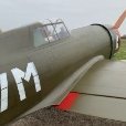
Spent yesterday morning flying the Warbirds Replicas Ju88 till I run out of batteries, after lunch from 2pm to 6pm flew a Kyosho Spitfire IC powered made the most of it as today the car is in dock for up dating1 point
-
Steve, Thankyou, I have blown the dust off it and re made the fins after you stirred a bit of interest in it. They are about twice the surface area of the originals, 2/3 of these are rudder so I am hoping this will sort out the yawing instability encountered on that last flight. If the weather is kind I hope to re-test fly it at our annual autogyro Fly-In this coming weekend, fingers crossed. Rich1 point
-
1 point
-
Whilst there has been a lull in flying gI thought I'd pull my finger out and get the zorst stacks sorted: The stubs are hollow so should help with the cooling.1 point
-
1 point

