PeterF
-
Posts
1,572 -
Joined
-
Last visited
-
Days Won
4
2 Followers


Recent Profile Visitors
2,233 profile views


PeterF's Achievements
216
Reputation
-

Thinking of leasing an Electric car, anyone had experience in this?
PeterF replied to martin collins 1's topic in Chit-chat
The economics of solar charging the car depends on your tariff. I am on Octopus Go plus Octopus Outgoing and charge the car and house batteries overnight at about 8p/unit and sell the solar in the daytime for 15p/unit so do not use solar charging. In other cases with low export payment it will make sense but in those cases you should be looking at better tarrifs. -
EDFs are typically small diameter, high pitch high rpm to produce high speed but low volume air flow to replicate jet engines. They are not set up to mimic full size ducted fans. A commercial EDF to power this would either be too small for scale and very inefficient or you buy an EDF of the right size at high cost and run it at low rpm. The way to approach it is as said above, get a motor to turn the same size prop at a typical IC speed.
-
1/4 Scale Tiger Moth build, a work very much in progress
PeterF replied to Richard Thornton 2's topic in Scale Matters
That is full size, no wonder it looks so realistic. -
A lot of 3D printers will only recognise SD cards up to 8Gb, if you try a larger one the printer will not recognise it. Have you fallen foul of this.
-
Not quite as powerful as Tim's above, which has given me discharger envy and ideas for improvement. I use a single 10 Ohm, 100W aluminium clad resistor from ebay. I normally discharge on my charger to the minimum voltage setting first then use the resistor. A 6S pack discharges at 2 to 2.5A dissipating 40 to 50W so the resistor does get hot. Much better in my view than a bulb. Always done outside on concrete or block paving. Ebay aluminium clad resistor
-
Replacing balance connector plug & pins
PeterF replied to Jonathan M's topic in Gadgets and Electronics
If you go through with disposal use a 12V car bulb to discharge the lipo through until it is well dead. Do not put in salt water, this has long been discounted as a good method of disposal, if the pack leaks the chemicals that can leach out are not ideal for going into the drains. BMFA discourage this in their lipo safety document. BMFA lipo safety booklet -
Go and have a look at the BMFA achievement scheme website. It has all the documents you need outlining the tests. If you find the guidance document for examiners and candidates for your chosen discipline it tells you more about the manoeuvres and what is being looked for. Click on menu > the tests > standards and guidelines and choose whatever discipline you are flying in, most often fixed wing power. BMFA achievement scheme
-
I sidestepped ABS in my printing and went with ASA which is meant to be superior to ABS and less smelly, but you still need the high temperature hot end and bed and ideally something to avoid draughts, I surround my printer with 2mm MDF sheet. Oozenest sell 50g samples of a lot of filaments, OK extra cost /gram but saves you buying a full reel for a small item.
-
A foam is a 2 phase material with a gas dispersed in a solid or liquid. If the solid is elastic then you have "sponge", if it is more rigid you have the types of foam used in RC aircraft. I even used metal foams when I worked.
-
Peterf's 82" A-10 Warthog plan build
PeterF replied to PeterF's topic in Build Blogs and Kit Reviews
Chris Golds produced a 62.5" plan which Sarik Hobbies supply a kit for ( Chris Golds A-10 ). I thought that scaling this from 62 to 82" was probably a bit much. -
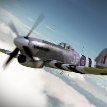
I have not done a substantive build since 2019 / 2020 and had lost the itch a bit. I had built a couple of models in the interim, but not what I would call substantive. I found myself with a bunch of equipment for a twin EDF build with a pair of high power 90mm fans on 8S that put out around 3kW each and a total 9kg (20lbs) of thrust for the pair. These have proven to be well capable of powering a 25lb slower flying EDF. I decided that IN would prefer to stay with a slower flying model rather than using them in a fighter type plane and for this reason I have chosen the A-10 Warthog. I cast around for plans in the region of 80" wingspan and came up with a set of plans on Outerzone for a model by George Miller from the USA, scaled at 77.5" wingspan. This plan was from 1985 and was based on a pair of 127mm (5") IC ducted fans driven by 46 sized engines. By all accounts it flew well as long as the engines remained working, but was a heavy beast as it needed a lot of lead in the nose to offset the rear mounted fans and fuel tanks which had to be close to the engines. I chose to increase the plans to 106% to get to 82" wingspan for a couple of reasons. The first was Roban used to sell a model at this size (the Roban model was slated as being poor with a reputation for wing folding in flight and collapsing retracts). JP Hobby sell a set of quality retracts for the Roban model so I could purchase a set of these and use them. Secondly, I believe I have the power for the weight of plane at this scale and a lot of the weight will not vary from 77.5" to 82", batteries, motors, ESCs, servos, retracts etc remain the same so I would reduce the wing loading slightly. I also have a feeling that I should be able to do this with hopefully a lower weight. There will be less weight in the engine pods and the batteries can go in the forward fuselage as a counter balance so there should be no need for 2 to 3 lbs of lead in the nose. I am also lightening some of the wood in the engine nacelles as they will not have as much vibration or mass to contend with. I used PDF scaling software to increase the plan by 6% and sent the files off to be printed by an on line service using a plotter and rolling the plans, printed on technical grade paper. The plans have come out well, however, as a warning, if anyone is inspired by this, the original scanning of the plans was not perfect and there has been some distortion of the plans. For example, some of the formers are slightly lozenged, double check everything before cutting. In addition, with this type of build you need to be experienced in plan building, you are on your own in terms of fan installation, retract installation, power system location etc. There is no build article or notes to go with the plan. Whilst there is a company in the USA that still sells laser cut kits and fibreglass components, once I decided to go to larger than plan, I am on my own for all items like this. The fuselage sides and bottom are 1/4 sheet balsa with some ply doublers around the wing opening. Most of the formers are 1/4 balsa sheet apart from the engine nacelle formers which are 1/4" birch ply in the plan, but have been swapped to light ply for my EDF build. The fan bearers will remain as birch ply. The fuselage is starting to take shape. It really is a simple shape and lends itself to the simple design in the plans. Photo of a model from many years ago. Cutting out formers. First stage after gluing the sides and mid section formers. These formers all have the same width, making this stage easy. Glued in with PVA, tacked with cyano. Also shown is one reason for getting the winter modelling mojo back, the diesel heater, makes building at this time of year much more pleasant. Gluing the formers for the engine pods together as a single unit with the fan bearers. These are in position in the fuselage but not being glued in at this time. The fuselage starts to taper in here making lining the formers up a bit trickier. The ply doublers over the wing openings can be seen. The wing openings will be cut out later. These formers and fan bearers were glued with 30min epoxy. The front 2 formers whilst being light ply are better quality with 5 layers and are denser than the lightest light ply, the fan sits between these. The rear former only supports the exhaust tube and is light light ply with only 3 layers. Engine pod, rear and front formers being installed. The bottom sheeting template can be seen by the side of the fuselage on the bottom sheeting. Fuselage sides with formers installed ready for the bottom sheet.
-
BBC news article. Plenty of other articles on line from yesterday evening. Teesside Live article (full of adverts).
-
tony nijhuis Nijhuis Lancaster 1/9 scale
PeterF replied to cymaz's topic in Build Blogs and Kit Reviews
The plan elevators is I believe because the early Lancaster had fabric covered elevators so doing it the way of the plan gives some stiffness from sheeting but shows the starved horse effect of fabric covering where it can be seen. Later Lancasters had sheeted elevators. The TopFlite DC3 I built was like this. -
Similar in Peter Miller's book "Designing Model Aircraft". If you have ever built a plan by Chris Golds or built a Tony Nijhuis kit like his large Vulcan then the ribs in these are basically a web of lightening holes surrounded by precious little wood.
-
See this page, gives some background to these. http://www.flyingsites.co.uk/news/flairnews.htm