Leaderboard


Popular Content
Showing content with the highest reputation on 24/12/21 in all areas
-
Final 2021 update. Things have been rather delayed for a variety of reasons. I was off work all last week and half of this week with suspected covid. My tests were all negative but i had all the symptoms so.. Anyway in the background the crankcases for the FT 160/200 were being manufactured and i was able to get one together to test the mechanical aspects of the case. For the most part it has gone well and everything works nicely. I will be moving the cams a little to improve pushrod angles and cosmetic appearance but that is about all. Once we are back in the new year the revisions will be made and the crankcases will get their cosmetic treatment as well. The final jobs will be to make a new mount for the back, and the new exhausts. Its likely the first engines out the door will be supplied with no exhausts but the price will reflect this. As a parting gift for the year, here is the FT160 doing its thing on the bench with a 16x8 RAM prop. Fingers crossed 2022 is better all around.6 points
-
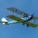
I took delivery of my Fiat CR42 at our last flying session and my pal Derek has sent me through some nice static shots of the completed model - with the 3D printed bust of Mussolini's son as a pilot figure, the final added scale details and squadron markings. It will be the spring before I fly this marvellous model myself. 50" span (~1/8th scale), weighs 5lb 4oz, for a wing loading of 18.8 oz/sq ft, Powered by a D3548 motor, 11x5.5" APC-E prop and a 4s1p 3600mah Lipo .3 points
-
Colin Buckle had a leg amputation this year, so I would be patient or consider building from a plan.2 points
-
This is new to me but it was built by a Club mate who had to give up flying. I re-engined it with an OS61FX but that struggled to pull the rather heavy airframe around big manoeuvres. It now has an OS 91FX in it - same crankcase so dead easy upgrade. Still running in the engine so probably quite a bit more power to come. Vertical performance is now much better but will no doubt improve as the engine loosens up. It really needs a new cowl as the pitts silencer it came with required most of the bottom of the cowl removed. There are now so many holes in the top to accommodate 3 different needle valves as well.2 points
-
Success at the front end revealed a new shortcoming - the low waistline of the design. This was making it impossible to blend the cylinder head fairings into the fuselage. The route I took was to pre-shape some really soft 1/8" balsa into approximately the right curve (good thing I have glue bottles of all sizes), stick it on, and sand, sand, sand. And fill... and sand... etc. The happy/easy part of the progress shown in these pictures is the battery hatch, which is cut along the inside edge of the cylinder head fairings, and perfectly aligns with the shut lines cannon access cover on the prototype (I hope...). Of course it came with its own complication, that formers F5/F6 didn't align with the end of the hatch cut - but who cares, the skin is holding its new shape and the formers aren't strictly required (they will likely return "in some form" when time comes to figure out how to secure the hatch).2 points
-
The calm before the storm... after a lot of sanding, it's looking good. The wheeze of building the rear fuselage sides with a curve has paid off, they look good and the fuselage is very straight and rigid. Realization then dawned that it would be VERY hard to make the cylinder head fairings in the right shape, with a front-to-rear taper, and blending seamlessly into the fuselage. Work stalled for a week while I thought about the problem (yes, this bothers my employers too!). It was clear I would have been better off, and with less work, if I hadn't wrapped the fuselage sides over the formers. The only solution (vs bodge) was to cut into those carefully shaped fuselage sides and let in vertical sheet extensions. The first cut is the hardest... The vertical extension had 45deg angle strip pre-glued to the top edge - this keeps it straight (because there is going to be a twist in the sheet at the firewall) and makes a way to attach the inner face of the cylinder head fairings. The 45deg angle turned out to be about right, and 3/8" sheet worked out well for the inner faces of the fairings. The 3rd photo shows a temporary spacer fitted between the front of the vertical sheets needed to maintain the correct separation (the clamp at the rear end is out of shot). Wedges of 45deg triangle were glued in to hold the outside front at the correct angle. Photo 4 shows the "end" result (it's from a bit later in the build).2 points
-
Any Scale Scottish Aviation Pioneers Out there? After a few years of inactivity due extensive work traveling, I am slowly resuming the building of my Scottish Aviation Pioneer, Having completed all the design drawings, I am ready to continue the project this next year. Please be patient as I will keep you informed.. Happy new Year all!1 point
-
Thanks guys for all your comments I sorted it retapped it to 3.5mm used a screw from a 15 amp choc block works a treat.1 point
-
Room for a thread repair insert? A bit pricey for a one off job but very handy to have for odd repairs and reinforcing threads in aluminium that may be subject to wear...1 point
-
I have an old ASP with the same issue. I just put an M3 bolt all the way through with a locknut. Thus far it has run with no issue`s at all. It did need a little retune first off, but I expected that.1 point
-
Not until its published Keith1 point
-
Well, after a long time I have got some more to show. This has been an interesting design operation as I have had to work out the radio installation on the model as it is being built. First picture shows the parts all built Second picture shows the top of the wing. Two servo cutouts and the hatch on the left is for the Rx while the one on the right is for the satellite Third picture shows the under side. This open area is to allow the servo lead and satellite lead to be threaded through to the Rx. Fourth picture shows the ESC mount. fifth picture shows the battery location. NOTE hatches over Rx etc and access hatch will simply be covered with iron on covering. Simple,lighter and quicker. Weight at this stage including the motor is 9 ounces1 point
-
Hi all, Does anyone know if Ben Buckles are still in business. They seem to be out of stock everywhere and taken off many websites.1 point
-
For those that have real trouble sleeping I have done a video of the journey. Its 30 mins long so have coffee and biscuits ready. Cheers Danny1 point
-
Great work Eric Which brings me on to.....Any of the 3D printing fraternity able to knock out some gun ports/wing furniture/small scale bits for an exchange of payment?1 point
-
Well done Danny looks good, now you can chill out Merry Christmas?1 point
-
Great work as usual Danny, now you have to fit a pressure nipple!1 point
-
Good, just asking ?1 point
-
That looks great Danny, well done! As far as mounting goes, a strap or bracket near the back as you suggest but perhaps also another, longer, one closer to the front and fixed to the engine mount side support, as otherwise there would be quite a long bit that is unsupported. Brian.1 point
-
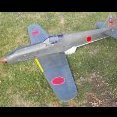
The weather is back to normal so back to building. The Hurricane is now painted , the engine was removed during painting and has to be fitted. the cockpit needs a pilot and some fittings, not a lot as there is not a lot to see through the canopy. the paint used was Guild fuel proof rattle cans, Great decals from Glynn Lander, and a little bit of weathering done.1 point
-
So with the positives from the test piece I decide to go for it! I really didn't want to wreck the work so far, but the best solution was for the flexi to be attached to the body of the exhaust. I could do with advice on how to mount the exhaust, I was thinking of silver soldering a strap between 3 and 4 and strapping to the firewall/tank box. Another strap around the flexi perhaps? Cheers Danny1 point
-
Now I don't know whether the pandemic has caused the local posties to discard rubber bands in the street, or whether it's caused us to take more walks around the village - but I've built up a stash of 8" rubber bands over the last year or so. These have come in handy for the next step, which is to attach the 3/32" side sheets. I used wood glue on the doublers, and Gorilla Glue elsewhere - as anyway it was necessary to wet the fuselage sides inside and out so that they are more flexible. It turned out one sheet was softer than the other, but it was the softer sheet that gave the most problems, because it was more bent inwards at the top edge. In the end I clamped it the top edge against a piece of hard 1/4" balsa, and that kept it from getting bowed. When the wood had dried I cyano'ed strips of 1/4" square inside the sheet on that side of the fuselage (which caused its own problems, as I hadn't thought to profile them to get the right shape. I had prepared the harder side by wetting it and then strapping it to a glue bottle of more or less the right diameter. Note to self for future projects - would have helped to have an intermediate former to take the load. It was quite hard to get the curvature at the firewall right; and the curvature of the rear of the engine compartment didn't work out as expected - F5 and F6 were too small - so that needed re-doing later. It would have helped if I'd realised the top half of the fuselage didn't need to curve inwards here. In the background of that photo you can see the front upper fuselage being pre-shaped by the "strap it to a glue bottle" method. The next step was to complete the fuselage akin aft of the cockpit, using offcuts from the bottoms of the fuselage sides. This helpfully left an opening a bit smaller than the footprint of the headrest/cockpit fairing. Since I was using Gorilla Glue here, I wrapped the fuselage with cling film to prevent it expanding everywhere.1 point
-
A slight change of plan on the elevator servo, I couldn't get it installed on one side of the fuselage as intended and at the same time leave enough room to route the snake inners that will take the closed loop steel cable. Instead I fabricated a 1/16" ply plate to place the servo centrally and leave just enough room either side for the snake inners: Servo in place with the ball joint visible that couples with the peg on the elevator: From below showing how snug it is: And from the side: Rudder and elevator hinged with Robart style hinges, fibreglass control horn bonded in to the rudder, so that about clears up the back end:1 point
-
With that cut to length and installed, the fuselage frame is really taking shape. The only part still to come is the spine from the cockpit to tail. And - it's slightly curved. Rather than trying to duplicate the shape from the plans, I found it easier to use an over-width strip of 1/8" balsa and then sand it to shape. What this photo doesn't show is that I later sanded away the top 1/4" or so of F9 (the former at the back of the cockpit) and the "spine" to create a flat base on which to mount the cockpit headrest/fairing. [that's another fix to the shape of the formers that I would want to make...] Now when it comes to that fairing I'd say: ignore the plans, it looks nothing like the real thing - which is a simple, small, tapered affair which joins the fuselage top in what is pretty close to a straight line. Just work from photos. Although I've spent hours sanding a fairing that looks like the one on the plans, it would have been simpler to fabricate one using 1/2" or 3/8" sheet glued either side of a piece of TE strip. I might yet do that...1 point
-
The plans show a cockpit floor, and also a floor to the battery compartment behind the firewall. I ditched the idea of a battery compartment floor - to make space for bigger batteries, and improve accessibility to the motor etc. The cockpit floor is partial; that might result in a more realistic look to the cockpit when it's all done, but who knows at this stage? Though I do regret not finding a way to fit the cockpit floor beneath the longerons. Also in the name of "realism", F7 is moved forward of its marked position so that a separate instrument panel can be fitted. And it has a cutout for the imaginary legs of the pilot. The upper frame fits to the ply box with a twisting action in which the longerons engage in the cutouts in the U-shaped ply former F4. (the plans have this as a full-fuselage former, but as it's going to be cut to create the battery compartment hatch there's no point to making it go all the way around. However... if I was doing this again, I'd extend the sides of F4 vertically above the longeron to support the fuselage sides. Also, the profile of F7 should have about 1/2" of nearly straight sides above the longeron, before curving inwards to its top - and F5 and F6 should be totally straight-sided up to the point where the cannon cover meets the cylinder head fairing. One the assembly of upper frame and ply box had dried, I added F11 and the bottom half of F10 to the frame and pre-bent the lower front corners of the doublers inwards (copious water as usual). While this was drying, I lad out the lower stringers on the plans, slighltly overlength and with a sacrificial cross-member to help get the right shape. That's not entirely to plan, because of the inward curve at the bottom of F10 and F11. Note: F8, F10, and F11 are all cut with a curve at the bottom, so that the under-side of the fuselage will be curved when sheeted.1 point
-
Picture time (didn't realize I couldn't come back to the posts and insert the picture links) The picture from the plans. Now that I've studied so many photos of the prototypes, there are 3 things that stand out as being wrong: the protoype has a higher "waistline" The cylinder head fairings aren't on top of the fuselage, instead the fuselage sides should extend vertically to the beginning of the curve that defines the top of the fairings. The top of the fairing should be straight and horizontal. Ribs, formers, and tail parts marked out for cutting. Fuselage parts after cutting (with former and longeron alignment marks drawn on the inside of the 3/32" fuselage sides). The fuselage sides extend forward of the firewall F3. doubler box - this worked out well, I would definitely do it again. Longerons and upper formers on the plans. Plenty of water sprayed to help the longerons bend. The board is 20mm blue insulating foam. A crossmember is placed at the right angle for firewall F3 to be glued on.1 point


.thumb.jpg.632415da66ae2d3b91c91514c153e5df.jpg)