Leaderboard


Popular Content
Showing content with the highest reputation on 15/04/23 in all areas
-
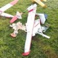
Me again! Maiden flight of my Spatman completed. In fact we managed three flights. I had set the throws as per the instructions and the model was much less responsive than I remembered. Over the next two flights I increased throws and by the third flight we had reached the fast, groovy model I used to fly back in the day. Just for nostalgia's sake, on the third flight I let the tank run dry and glided down to the strip dead stick. Total fun... Here is Spatman keeping company with my Limbo Dancer.3 points
-
Dandruff cure?3 points
-
I thought it would be simpler to install the servos and control rods for the elevater and rudder before sheeting the underside, so thats what I did So here is the little GiGi mocked up and ready for final sanding and covering Colour scheme will be blue fuselage and yellow wings3 points
-
There's "some" difference between the kit version and the 3D printed version.... 😜2 points
-
Thread resurresction 😉 Maidened today, ex @Mark Jones 10 Gangster that appears further up in this thread, bought by me unflown a while ago. It flies beautifully, although two flights today was enough as I find maidens quite stressful. I need not have worried though as a few beeps of down and a couple of aileron resulted S&L hands off at mid stick cruise speed. This thread was a great help in getting it ready - I went straight in with the CG at about 100mm as I like just a little positive stability. I may experiment with it a little further back as it's carrying a bit of down elevator trim at the moment S+L upright and with the stick centred, and needs a bit of down stick for S+L inverted. Hope that makes sense. Let the detailed trimming begin...................tomorrow 😉 I'm really pleased it flies so well.2 points
-
More test flights yesterday 🙂 https://www.youtube.com/watch?v=8VxDhxCblAc Timo2 points
-
Re the spiralling costs - some {many ?} of us still have a kit "mountain" to use up (or sell on) & maybe also a stash of raw material to scratch build from without dipping too much into our pockets. 😊2 points
-
It doesn't have any model aeroplane drawings on it, so I assume it's not local to you ? 🤣2 points
-
Calling mine mostly done. Just need to glass and paint the spats.2 points
-
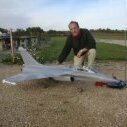
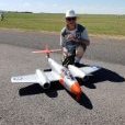
What a lovely afternoon to fly the Spatman with the SC15 for the first time. I can now confirm that a 15 is the motor to have 🙂 Few things still to sort, engine down thrust, tick over, and motor cut. But great fun had until the fuel ran out.2 points
-
This is an extra large version of my foam model stands and is made out of 20mm EVA. The overall length is 750mm and is designed to not only hold larger models than the standard size stand but it can be fitted to a cheap (£15 ish from Amazon) music stand to provide a comfortable working height when at the field. As per the standard size one it comes with flat topped ends for you to cut out to suit or I can provide partially cut cut outs to make it easier. The hole and slots in the sides fit over the music stand ends, the slot allowing for height adjustment. Note that the hole and slot are cut to suit 25mm tubes but I can cut a different size to suit. XL Stand with flat topped ends £30 inc P&P, U choose U cut ends £33 inc P&P Shown here fitted to music stand (not included, neither is the model!)1 point
-
I'm working on this Fokker in 1:5 from ECOM-RC. It's an ARF that I'm converting to a Swedish version. There was just one example. I have removed all of the plastic film covering and started the Koverall covering. I have also bought pinking tape from Toni Clark. One of the downfalls of the kit was the dummy engine, which was a glossy black vacuum formed lump..... There was no interior details at all, so that also needed some work. The wheels are a whole other story that I'll get back to. As the dummy engine is very prominent on the D.VII it demands some special attention. I found a CAD file online (in 1/3 scale), that I resized and printed in ABS+. I also designed a tube frame and a chair. After 16 hours it was ready! Now it will be a whole lot of work to finish them. At least I don't have to build any machine guns, as the Swedish version was unarmed.1 point
-
VID_20230415_173026.mp4 Did a quick maiden - worked a treat! I didn't have the guts to fly it myself, I got my mate Toby to do it as he's an awesome pilot. I didn't get the whole flight unfortunately.1 point
-
Sooner or later you will have the rate set wrong. Use a bit of expo and you still have full movement available when you need it but with soft centres like a decent box of chocolates. Anything that lightens the workload while you are flying is good. That's where modern computer txs come into there own.1 point
-
The windscreen is quite an elaborate affair consisting of a wooden base to which the screen is fastened by adjustable side brackets and then just to complicate things further the side brackets have metal fairings! The base is from 1/32 and 1/16 ply, the brackets are tin plate with cut down servo mounting grommet bushes soldered in place and the acetate screen has a litho plate edge. The complete unit will be glued permanently in place after the fuselage has been painted. Then I’ll have the problem of the fairings! Probably another “plunge moulding” exercise. The 20swg bracing wires have ends made from brass tube, a time consuming job as there are 40 required all together. This is where the vast majority of the drag comes from but on the plus side also a great deal of strength. As the bracing wires need to be included for scale effect I see no reason not to make them functional. I’ve had to move to the conservatory for this job (the cat’s non too pleased), there is just not enough room in the shed to work comfortably with the wings in place. The bracing wires are held temporarily with pins; they will be labelled and removed, then attached permanently after the model is painted.1 point
-
Back in the shed tonight as I have received my PC monitor wall bracket. I like having my PC handy when I am watching some of the handy UTube how to videos. My carbon club may be getting pressed into operation due to a change in training instructor. I still have a bit more general tidying to go so I'll get things hopefully closer to a finished state tonight. Happy days. Toto1 point
-
Part of the issue is the inrush current to the ESC capacitors, this is what causes the spark when we make the connection, it's basically close to a short circuit until the capacitors charge up. So the problem with this type of switch is the arc that would occur internally as you make the connection. Multiplex do an Antiflash connector rated for 70amps, which basically uses a solid state circuit to limit the inrush current and hence the arcing, this can be fitted with a separate switch. You could I suppose make a 3 position switch, i) off, ii) connected via a resistor (to reduce the inrush current), iii) connected with no resistance. Back in the early days of electric flight it was common for ESCs to be fitted with a separate on/off switch, I've still got a couple of Jeti ESCs with this feature.1 point
-
About a year ago, Jeti used to list 2 genuinely high power switches. One was rated to 100 A and the other to 200 A. Both could be operated by the Radio system but they were pretty expensive. I don't see them advertised any more which tells me that the take up on these products was insufficient to justify commercial production. As you would imagine, they were primarily to connect and disconnect the drive batteries. I see they do a separate switch for the Rx and servos for up to 15 A.1 point
-
The tops of the undercarriage legs are filled to fit to the fuselage “hatch” and then have the litho plate added. Once again it was quite difficult working from the side view to get the correct shape to wrap around the legs, they’re still not perfect on the inside but that won’t be easily seen. The large rivets were embossed using a pop rivet, before it’s been snapped off, and a sharp tap with a tack hammer. The nut and bolt used to attach the undercarriage to the fuselage is too big to be embossed so I moulded them. I made the mould using a suitably sized bolt pressed into plasticine. There’s no fine detail so a mixture of epoxy and micro balloon is OK, if there is fine detail you'll just have to bite the bullet and buy casting resin and proper mould making material. Once the epoxy mixture is really hard the plasticine can be easily removed and the “bolt head” tidied up. The one on the right has a slight imperfection but a dob of filler soon cures that! A short length of plastic rod converts half the mouldings into nuts. The mouldings are then cyanoed to the undercarriage; only one coat of paint at the moment just to check they don’t need any more filling.1 point
-
Well, I don't know about new! I've been using mylar strip hinges (not even furry ones!) since the 80s without any issues! Initially I used to peg them with cocktail sticks, but these days I just punch a few holes in them with a pin, and then let the cyano do the rest. Not had one fail in decades, and on up to 60 powered aerobatic models... (There! That's done it! One will probably let go next time out now.....!) -- Pete1 point
-
Apparently it is legit. My "uncle" in Africa has bought me a couple and as soon as I pay him for the shipping he is going to send them to me.1 point
-
Are you sure it is the ‘prop adaptor’ that is bent? It looks like a substantial chunk of aluminium. Is this the Motor fitted to your Tundra:- https://hobbyking.com/en_us/durafly-tundra-3636-900kv-replacement-motor-w-mount-and-propeller-shaft-suits-v1-v2-night.html If you remove the prop and run the motor does the end of the motor shaft wobble? Is there still vibration with the spinner removed? Have you tried balancing the prop? The motor may have partially come adrift from the model or you may need a new motor. In any event further investigation could be a good idea. 👍1 point
-
Thanks! The dummy engine is assembled. The next step is to cut the piano wires and then apply a layer of filler/primer. The painting is what I'm looking forward to the most. 😁1 point
-
Not really, electricity, heating and lighting, rent, rates, insurance, wages and the 'states' part, bank charges, taxes, rules and regulations, it just goes on and on,, years ago a family with a couple of kids could live on one wage, not today.1 point
-
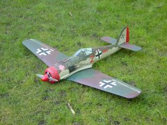
Rivets all completed so whilst awaiting some decent weather to start laying the final Luftwaffe RLM colours down I have started to make sense of the wiring and airlines. I have 11 servos operating over 10 channels (the little cooling flap servos are on a y lead) plus two more channels required for the ignition and on board starter. A Powerbox Pioneer is being used to manage the twin Li ion power packs and servo distribution and this will have a pair of receivers connected each with dual receiver circuits for added redundancy. The four flap and aileron leads from the wing run into a single female plug with the male very securely fixed to the side frame to mitigate against any disturbance to the receiver connections. The air setup is pretty straight forward with a simple UP-8 valve feeding air to the tail and main retracts. Air fill valve and switches (radio & ignition isolator) are located under the gun hood.1 point
-
My photo shows how I insert the saw - it's a setup as i needed my right hand to operate camera- the saw is actually in the wood though which is only 1/8 inch thick at this trailing edge. To really do the cut I just pressed the tailplane against the edge of the bench in a similar vertical manner to the photo and sawed in on the diagonal. Sawcut should go in until both bits have a sawcut. As the saw cuts down the cut is flat bottomed and takes a straight bit of ply. The ply is simply inserted where the saw is now, marked for trimming, withdrawn then cut with scissors and then reinserted with glue applied and pushed right in until hidden. Takes just seconds.1 point
-
Exchanges between lawyers and witnesses. It's now easy to see why better lawyers cost a bit more, eh... 🤦♂️1 point
-
How many times must it be pointed out that it isn't the presence of adverts which is the problem that users are experiencing? It is the reduction in usability of the forum, which seems to have been caused as a result of the modification to how the ads are displayed.1 point
-
With sufficient elevator power a stall (or airframe failure) can occur at any speed. When turning, g loads increase, increasing the effective stalling speed (technically a stall relates to the angle of attack) by requiring additional lift to maintain height. At 60 degrees of bank, an aircraft effectively weighs twice as much. A practical example was my 1/12 scale combat models which I set up the elevator movement to just not flick into a stall at full throttle and full elevator in a tightly banked turn.1 point
-
Hi All, Had my first successful flight with the Gyroo last Saturday! Managed a full flight battery this time and I think I might be getting the hang of it. Landing was perfect as well just almost hovered down. I did have a club member standing next to me trimming it for me a bit while I was flying and giving me some tips. Now it’s trimmed it’s flying great. In all the excitement I forgot to stick the camera on my head so I will have to get some footage next time. Looking forward to it!! Paul,1 point
-
I only have 'dual rates', per se, for test flights. Then choose the best rate, and remove the others. I do, though, use multiple flight modes with different mixes, curves, and rates. Not a fan of SAFE etc at all - instils false confidence in my experience. Gyros/AS3X etc have their place, but not as a default. Other opinions are available.....1 point
-
I have been seconded to decorating duties for the last couple of weeks so not much done to my litte GiGi, but I have managed to finish the top decking All carved from the solid As luck would have it, I found a piece of 1'' leading edge pre shaped balsa in my scrap pile and so I used that as the basis for the head rest fairing, this is the pile of shavings accumulated from all the carving! Tomorrow I will press on with some more piano wire work on the cabanes1 point
-
Here we go in the fuselage jig, starting in the middle with the two cabane carrying formers, get these square and all the rest follows easily All the rest go in And this afternoon out of the jig, and a couple of gratutitous mock up pics to see what it will look like Top and bottom sheeting to do The bulk of the building is done, get the top and bottom sorted fit the radio and cover plus make up some undercarriage1 point
-
Now some shots of build progress so far. Most self explanatory, I'll add notes as necessary. I have two plans for this model: a version redrawn in CAD by Richard Browning, and a Graupner version in German, which looks like it may have once been part of a kit. I'm building from Richard's plan, partly as it contains drawings for both wings (luxury!) but referring back to the Graupner plan for anything that isn't clear. Tailplane part built and complete: I've opted to use a wire "U" shaped joiner for the elevators, rather than the dowel specified on the plan but otherwise no changes. Rib templates, cut out on the scroll saw: and the resultant rack of ribs: easy, since this is a constant chord wing.1 point


(2020_03_2622_00_27UTC).thumb.gif.375a6ebc5cd681eb724c62879a10ef8d.gif)