Leaderboard


Popular Content
Showing content with the highest reputation on 10/02/22 in all areas
-
Well, it's finally finished! I've still got to select a prop size to give the power I need. It's come out a bit lardy at about 75 ounces, with battery, so I'll prop it for 450-500W. The weight probably comes from several sources. Adding flaps, heavy wheels and a bigger motor than it really needs all contribute. I chose the powertrain to make use of some 4s 2200 packs that weren't used anywhere else, they have a similar energy capacity to the 3s 3000s that Peter used. I'm not too worried about the weight as its a bit less than my Ballerina, with only a slightly smaller wing. The colour scheme is a bit of a hybrid - photos of it in the museum show black wingtips and no lettering on the wing, as on my model, but I've added the checkerboard fin because I liked it! Covering and trim are HK film, given a coat of Plastikote matt lacquer because the museum example looks matt. I'll give a flight report when I've had the chance to try it.3 points
-
With the arrival of the film from HK I was able to finish the covering, followed by the application of the registration lettering courtesy of my Silhouette vinyl cutter: Followed by glueing in the struts to the hard points: Windscreen was fabricated from 0.5mm PETG fixed with UHU Por and silicone sealant and silver metallic vinyl film applied to simulate the aluminium support. Which, apart from radio setup, completes the build: AUW 2.2Kg (or 4.85lbs in old money), she balances easily without any lead and with room for adjustment on the battery if needs be. Maiden flight probably won't be until the spring. Thanks to PM, she was a joy to build and I'm sure will be just as enjoyable to fly - looking forward to some low and slow flypasts!3 points
-
Im sorry Martin but your statements are incorrect. With the tank high needles are set very lean (in number of turns) to offset the assistance from gravity. If you do anything that results in the model being inverted the fuel tank drops substantially in relation to the engine so this gravitational assistance is lost. the lean setting on the needle means the engine is unable to draw fuel now gravity is against it. An acceleration change of nearly 20m/s^2 due to gravity inverting is simply too much for the engine to handle. Consequently it will run lean and either loose power, or stop. If it does keep running it will then go rich at the bottom of the loop due to the increased G force as you recover. It ends up being a dogs dinner with the engine running lean, then rich, then lean again. It wastes fuel, gives variation in performance, compromises reliability, etc. All of this is very simple physics and, to be honest, many of your models exhibit these problems. I have seen it with myself and while you may be satisfied with the level of performance you are getting it is not the level of performance you could achieve with the tanks positioned properly. When it comes to lowering the tank in a Spitfire, its absolutely possible. My Hurricane's are modified to allow the tank to sit in the wing and my 3 future Spitfire builds will be as well. The ugly mustang i am fixing will have its tank mounted low enough to suit the inline as well as all the other mods needed to suit the engine. We also have customers flying BT Typhoons with wing leading edges modified to suit and the nose on them is super short. The only models i have even known that absolutely cannot be modified to have a lower tank are things like tucano's and PC9's when the retracting nose wheel is right in the way. In these cases you would need to make your own tanks to sit either side of the leg, or just mount the engine on its side. So the ultimate conclusion is that any model can have the tank placed correctly if the required modifications are made. The amount of work required may be quite small, or substantial, but it can be done provided the carb is within the aircraft outline. Under slung external fuel tanks probably are not an option. I am not trying to throw you under the bus Martin but you are directly contradicting the recommendations of the manufacturer of the kit you are using while it exhibits many of the problems that cause said manufacturer to not recommend the very thing thing you are promoting. I make these recommendations on installation as they guarantee the operation of the engine in all models, under all circumstances, anywhere in the world on any fuel every day of the week. I cant recommend something that worked for one bloke in 2 models to only his satisfaction. Its why i dont recommend Steve Dunne's pressure isolated header tank setup. It works, i know it works, but the level of complexity and the skill required to make it work means its functionality is more down to how well its put together than its original design. If someone follows your advice, or Steve's, and their engine runs like a dog who do you think will get the phone call asking for help? Me. At the end of the day you have no responsibility for the advice you offer. If it all falls over and someone's model crashes as a result of their engine stopping at a critical moment there is no backlash on you and the person reading your forum post wont call you up to complain, they will call me to complain. I probably deal with at least 10 people a week having problems with engines due to tank placement and too many times i get the 'oh a bloke at the club/forum/youtube said it would be fine'. Its not fine, it will not work. Install the tank in line with the carb. I know some of you may feel i am having a personal dig at Martin here and that is not the case. I know you all try to offer well meaning advice to help other people out with their problems. Its why the forum exists after all, but, alas, some of it is wrong and when it comes to Laser engines and their installation the buck kinda stops with me. This is the 'official' Laser technical questions thread and consequently i get the last word as i am the only one officially representing the brand. So i will counter any posts that contradict our recommendations. I am not trying to name and shame or humiliate anyone, i just need to make sure anyone reading this thread see's the same consistent advice from the manufacturer of the engine they have. Advice that i know will remove all the guess work and make sure their engines perform as they were intended to. Also anyone who has always done things a certain way and been happy enough might find a whole new level of performance by following the recommendations i make. You dont know what you dont know at the end of the day and all i am trying to do is make sure everyone has their engine run at its best. This even applies to other brands as OS, saito and ASP engines all perform way better on the right fuel, tuned correctly with the tank in the right place. Just get the basics right and the rest becomes so much easier. If you feel hard done by Martin give me a call and we can discuss it.3 points
-
I think the advice that you've given out yourself in that second sentence is sound. With just the one pair of eyes, which are quite vital to the mission and with props available at such modest cost, I'm struggling to see the possible benefits of 3D printing one, especially with PLA.3 points
-
Must be about 4 or 5 months ago and to be honest it was all my fault as I wasn't really paying attention. I had just sprayed the primer undercoat on the JU-88 and was contemplating adding some more panel lines but my attention wandered and I think that is when I lost it. I tried a backup plan and ordered a plan plus some cut bits for the Kyten delta wing and started cutting and gluing but it still wasn't there so that build also stopped. No matter what I did or where I looked I just could not find it anywhere, you know what it's like you think you've put it in one place but when you look you find you were wrong. Frustration then sets in and you resign yourself to having lost it 'forever'. The wife kept saying "never mind, it'll turn up and in the meantime you can help with the gardening" (at this time of year???). I even had some suggestions from Richard Wills (Warbird Replicas) who suggested that I looked in the compost heap, which is about as much use as a chocolate teapot as I haven't got a compost heap, mind you, come to think of it I wouldn't mind a chocolate teapot, I wonder who makes them? Anyway getting back to the saga (they do good insurance on old properties you know). Christmas came and went and I got a new kit as a present from my wife, well it was from me actually but she told the children that she got it for me but if she did why didn't she wrap it up, didn't even put a bow on it! But even when I opened the box I could see that it wasn't in there either so the box was put on the 'to do' shelf with the 6 other boxes. Then earlier this week I was rummaging about in my workshop and lifted up one of the wings of the Kyten, dusted it off and as I looked back to the bench at the other wing lo and behold there it was nestling in between that and the part finished fuselage. Boy was I happy, I went skipping (sad but true and also very difficult on a gravel drive) back to the cottage and couldn't wait to tell the wife who's reaction was "well you couldn't have looked very hard for it in the first place and if you had let me into the workshop (she's not allowed in unattended and has to sign the visitor's book - health and safety - both for my health and my safety, and usually has to give me 2 day's notice) when you couldn't find it, I would have found it straight away". The upshot of me finding it is that the Kyten has been finished and I will be carrying out its maiden flight tomorrow! (Photos etc, to follow).2 points
-
Graham has covered it ( no pun intended) but a big difference in the maker foam is that it is more flexible than foam board. A good website to look at google Julius Perdana models. He is a genius with depron and has made some fantastic models, he makes everything including retracts, check out his Phantom. Back to the Mosquito I have not been able to work on it today much but have managed to clad the fuselage as far as I want to go. the next stage is the wing which will fit into the top and be detachable as a 6FT span model will not fit my car built up. I will finish the front of the fuselage when the wing is in place. I took some photo's during construction of the fuselage and e mailed them to myself then wiped them off the phone not realising I'd wiped them off the computer. The fuselage is glued with Uhu Por and hot glue, I find for long lengths of glue Uhu is better as it has a longer drying time but don't wait too long as if you don't get it right it grabs on contact.2 points
-
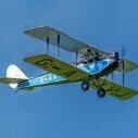
Slingsby T31M from the Peter Miller plan:2 points
-
2 points
-
Sorry as I really don't get this, Jon (Laser Engines) gives free advice based on experience and as the subject matter expert for Laser engines (does anyone on this planet know any more about the current range of Laser engines - NO). So if the advice is to line the carb up with the tank then that's the advice....if you deviate from the professional advice then you do so entirely at your own risk. If you want a sub optimal set up and performance then go ahead, but for me and especially with twins I want as many odds stacked in my favour as possible, just makes flying that more enjoyable known its less likely to dead stick on me. Shall we move on to castor oil and high nitro again...?2 points
-
I'm a keen plastic modeller too: I really like old vac forms in particular. I started building with an Airfix Mig 21 when I was 4 ( nearly 54 years ago ) Here are a few of mine from the last few years:2 points
-
Wing bottom sheets cut in foam board, these are 33" long as opposed to the maker foam which is 30". I will use maker foam for the top and probably join it at the nacelles as I am short of 5" span. Jonathan, here is some construction pictures which I managed to save.1 point
-
Hi Rich, Just to put this into context, for my day job I work with Chinese suppliers and factories, and have done so for 15 years, It will help to put perspective on my comments... I have and do use Hobbyking, and generally with total success. In some respects (their film), they are well above average. But let's be honest here; we all go to Hobbyking because of their prices. In general, we never get something for nothing and in dealing (albeit indirectly) with China we have a trade off for the low costs. To me, that is risk. I have to accept I may pay a price; I may get poor quality, poor service, late deliveries and so on and so forth. But I may not. If I don't, and all is well, I'm quids in. However, as with Banggood, I don't pay what I'm not prepared to lose. It's as simple as that. But that's my view. And so far, I've had no issues...1 point
-
Dynamic soaring uses sharp edged transitions at the point where two different air masses coincide. Control liners aren’t flying free - they are held at a fixed point on the ground and the additional energy is applied through the pilot’s arm. I spent many hours circling in gliders and never had to make any corrections for wind induced speed variations. At low level in a meaningful wind, where relative ground movement became apparent, it was important to ignore your eyes’ impression of airspeed and continue to fly by attitude and airspeed - neither of which varied in a constant circle. Getting back towards the topic on torque reaction, isn’t a lot of the thinking behind the possible B test amendment learning to react safely to a situation such as that faced by the Mustang pilot mentioned above?1 point
-
Thanks John, since dropping my lap top I can't cut and paste.1 point
-
Rapid RC Models in Kent have a good selection of retracts.1 point
-
Have most of the airframe built now, lots of trimming and adjusting fits etc to do. The long plastic parts outboard of the intake are called 'wing gloves' the slot for the tailplane controls their position fore and aft (the tailplanes are notched for a ply cross member/spar), which also controls the position of the fins (another slot cut in the plastic and keyed to the tailplane). The wing gloves are not quite touching the intakes which is related to the same fore and aft positioning, all good head scratching fun!! The top hatch (with the two engine bulges) is keyed by tabs at the front and held closed at the rear by the two exhaust nozzles which will be under rubber band tension towards the front. Elevators are controlled by torque rods that will pass out of a slot in the exhaust nozzles.1 point
-
John, i know you mean well but with respect mate this isnt about what you would do. The official recommendation is not to use chicken hopper tanks and that is more or less the end of the discussion. Just because you managed to make it work it does not mean that everyone else will and i cannot offer technical support on some random setup that is working to your standard of acceptable and not mine. i have never seen it operate so it might be perfect, but i dont know that so how can i recommend it? I know it will be perfect with the tank lowered so i will recommend that. Anyone calling with a problem and a non standard tank setup will simply be told to move the tank as i have no hope of dealing with it if i have no benchmark in the hardware. There is also a more than fair chance the tank is the problem anyway. I explained all of this in the earlier posts and have to admit i am more than a little frustrated that i have to explain it again only a few hours later. The thing that baffles me the most is that it takes so much more time/effort to dream up and build some of these fantasy solutions than it would do to just move the tank. I am genuinely at a loss to explain it and really at my wit's end with the whole discussion. If moving a tank is really that difficult a task just buy a different engine.1 point
-
That looks great. I am looking forward to hearing how you like her.1 point
-
Very nice Stephen, enjoy. ?1 point
-
The thrust test on the printed prop. https://www.youtube.com/watch?v=OP9jXhHeakM A bit dark as I wanted to show the LED display on the balance. The Wattmeter showed 73.9W. The balance reading is taken as 305g thrust thus giving an efficiency of 4.13 g/W. A second run gave 76.6W and 313g giving an efficiency of 4.14 g/w A commercial 6x4.5 absorbed the nearest power level and gave readings of 77.2W and 373g trust resulting in a rather better 4.83g/W. An improvement of 16.9%. This does rather confirm the advice that a printed prop is unlikely to match the efficiency of a commercial one and by quite a substantial margin. This result was despite quite some finishing effort to give the printed prop a smooth surface although still well short of the gloss finish of a commercial injection moulded one. Just a note but a crude test showed the commercial 6x4.5 could easily withstand a combined load of 1kg applied at just the prop tips. The same test on the printed prop showed considerably more deflection at just 800 g.1 point
-
Not quite sure why your video didn't embed directly above, but here it is for ease of viewing. I agree the lack of deflection is impressive, though I'm not sure I'd have been brave enought to put the camera there on the first run-up! Having seen this some of my fears on safety have been allayed, but I still wouldn't trust this on a model with others in the immediate vicinity - the big unknown is how it will stand up over time.1 point
-
thanks but found one from a club member and a bit to far away in lancs eric1 point
-
Don's audition for the masked singer!1 point
-
I’m getting a bit uncomfortable here. We are discussing collision avoidance between a toy airframe and a human being. And suggesting turns at low altitude and low speed, in an emergency. As the old bit of wisdom goes, no hight, no speed, no ideas is a route to disaster. Low, slow, don’t mess about, hit the ground. If you then chose to pull the trespassers arm off, and beat him to death with the wet end, that is your choice, but not with an airframe.1 point
-
I can help with that! Flight Test's MakerBoard has a different paper cladding. It is very easy to remove, which is great for some applications. It is slightly waxy though and although I haven't tried it, I suspect may not be ideal for taking paint directly. I got mine from Sussex Model Centre. Hobbycraft (and others) has a paper cladding that is very firmly fixed. It can be removed with gentle heat from your covering iron, and takes paint well. What to use? Both have benefits and drawbacks. My Ki45 is entirely from MakerBoard, and most of it is completely stripped of the cladding. This was because I had decided at the outset to cover the model on PVA/ Brown paper. The cladding comes off very easily, so any exposed edges WILL lift quite soon. The prevented me from glueing to it in any stress areas. Not the same with Hobbycraft that is very secure. For creating an airfoil, it is much easier with the cladding removed from the inner face, so that's quicker with MakerBoard, but you'll need to cap the edges if you leave the outer cladding in place. I'm going to make an ultra-quick build sports model and will use Hobbycraft board for that because I will paint directly. For the Brown paper covered 'birds, I'll use makerboard. For formers and internal parts, probably hobbycraft as the paper makes them stiffer for a small weight penalty. Of note; these foams do have a grain. Eric found his cracked if you try to curl them along this (rather invisible) grain. I didn't have that issue, but it's certainly easier across the grain. In any case, it's so cheap (around £4 for a sheet for either), best thing to do is have a go. Graham1 point
-
....all I'm going to add is please make sure you capturea video of the first test, it may be interesting...! ?1 point
-
Natural England , RSPB are IMO blinkered and selfish organisations who regularly overstep the mark. Dog walkers, horse riders.off road cyclists and grazing cattle all affect wild birds far more than flying models. Our flying field is a haven for wild life and birds who seem to take no notice of our models apart from the Buzzards who regularly catch thermals with the Glider gliders. Unfortunately I don't think you will beat them as they have the ear of the old boy network who pull all the strings . Good luck and hope BMFA can help.1 point
-
Plodding along, today was spent hinging the ailerons (which are the flaps on a real F-15) and elevators. When I first got a Dubro hinge slotting kit I thought it was a revelation but I've always noticed the mess it sometimes makes in balsa. The problem is that the hooked tool (leftmost), designed to pull out the balsa crushed by the forked tool, often pulls good wood from either side of the hinge slot. This makes an untidy slot. I tried a different tack today, using the jig with holes instead of the slots I drilled the slots out which leaves a much tidier slot. The other photos show the wing mount bolts and nuts, I've had the wing on and off many times so I resorted to my electric drill/screwdriver to wind the bolts in and out.1 point
-
Well, I’m starting to get impatient now whilst waiting for the kit. I’ve laid the first part of the plan on the bench (& gave myself no working room! - I could’ve sorted it out but I’m too tight to use too much plan protector ?), put shallow cuts in the crutch and pinned the crutch to the board. Side view of fuz on the wall for reference and all part patterns cut out and in box for reference. I’ve also thrown together a 1/32nd plastic kit for reference. I won’t say the name of the kit as it is awful and I’ve had to cut, modify and sand to get it all together. I’ve also left parts out in the box which I’ll use for reference as well. Come on kit! Hurry up ?1 point
-
Managed a little more, but managed to get really bogged down with learning Fusion 360 this week. Did a drawing of the throttle quadrant for my Auster, to then realise it needed to be printed in parts, so my poor drawing methodology meant I would have to start again. So I created the part from styrene sheets, rods and some glass headed pins.... as you do. Will be glad to escape the cockpit... Oh I did do a Venturi which a friend is printing ? Cheers Danny1 point
-
IMHO, if its good enough for a P39 and a FW 190 then its good enough for a Spit, of course a completely different argument if it was a Hurricane ?1 point
-
Away from people and away from the flight line if possible.1 point
-
Webra speed 61 back together apart from running out of 3.5 capheads ! The other three will have to wait, replacing the bearings is a bit much for my pocket at the moment!1 point
-
John, you're right that the flying is no easier it's just more likely that you will get to the field and fly several flights with much less hassle than in the "old" days. I think that having a level of today's equipment reliability means that your continuity of flying is far greater. If you only managed one flight per session, as was quite often the case before something went wrong, then it took longer to get your hand/eye coordination training. That's what I meant and should have said more explicitly. As regards the B, I took mine with a Wot 4 with all its faults. I still demo the B with the same Wot 4 some 11 years later. If you stick to flying a specialist aerobatic airframe for your B then you need to learn how to land properly every time as these airframes are designed to fly and not crash and be easily repaired. Airframes that are too light are a bit of a liability as they get moved around a lot more by wind gusts than a trad Wot 4 type. Don't mind if it's leccy or IC but you must have the duration with a leccy otherwise you need to land to replace the battery pack to get through a B. Duration of flight is still the one advantage of an IC model. I would look for around 12 mins for duration for a B to allow the repetition of any manoeuvre if the Examiner asked for one to be repeated. I used to be able to get in 2 full B flights but without a full landing between them on one tankful in my Wot 4 which was about 15 mins.1 point