Leaderboard


Popular Content
Showing content with the highest reputation on 11/02/23 in all areas
-
Remind me, are cans of worms crimped or soldered? 😉3 points
-
Good stuff. Sounds like the only thing left to do is make sure you ignore all advice given by your “friendly” local model shop owner in future! 😉2 points
-
I've only got small planes, short arms and deep pockets!2 points
-
Those connectors are designed for specific small conductor sizes used in the telecoms external network - well below the current requirements for an electric flight motor. They work very well for their designed purpose. I would say they are totally unsuitable for what you’re suggesting! You can buy similar but larger (dry) versions for automotive cable use but they are, in my opinion, an unreliable bodge which I would avoid using.2 points
-
Was going to say "marriage on the rocks" ? best not eh.2 points
-
A recent project has been to fabricate an RC carb for a PAW 2.49 Yes, I know you can buy one off the shelf, but hey.....2 points
-
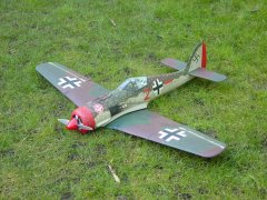
The fuz is assembled and installation well on the way, hopefully not too long before I can try it out. The wing in the bottom picture is from the previous balsa version.2 points
-
Before I forget add some dye of choice to the list above ., and a jar of Bicarbonate of Soda just in case of accidents . Make sure the room or area is well ventilated as it gets quite fumy. A couple of decent site to get the idea of the process are ebd Guide to Anodising: Anodizing Explained How To Anodise aluminium part at home (engineeredbydesign.co.uk) How to Anodize Aluminum (with Pictures) - wikiHow Anodizing for the DIY crowd (bryanpryor.com) These site will show how to set up your tank . Now you need a rinse container of distilled water, a container of caustic soda solution and a container of Desmut solution I also have a container of tap water handy and the jar of Bi-carbonate of Soda . So you have your part polished, see pic below . This has been polished on a buffing wheel to a near chrome like finish but will still have a layer of oxide that needs to be removed before anodising, Now put on a pair of rubber gloves as your finger prints will stop anodising from working. Don't forget anodising doesn't cover any blemishes . If there is a scratch it will end up as a an anodised scratch. Give the part a really good scrub in a de-greaser with a tooth brush and rinse in some HOT water . Repeat a couple of times until water doesn't bead on the item. Now fit it to a piece of the aluminium or titanium wire and hang it in the caustic soda for a couple of minutes . Remove and rinse in distilled water. Now dip into the desmut solution for a minute or so . This dissolves any metals other than aluminium on the cleaned surface. Rinse and then hang in the anodising bath making sure it doesn't touch the Lead or Aluminium anodes . Remember Nothing but Aluminium , Lead or Titanium in the bath. Connect the negative - to the anodes and The positive to the item or cathode and switch on the charger or power supply. For a couple of cylinder heads etc I set it at 12 -15 volts at between 0.5 and 0.75 amps . The anodess should start to bubble quite freely and a few bubbles will be seen coming from the cathode or item . Now leave it for an hour. While its cooking prepare your dye . This is best used warm as it helps it to soak into the pours created by the anodising process . Remember just warm but not hot, If Item has previously been anodised this can be removed by a soak in the caustic soda bath but beware it will reduce or eat away any bearing surfaces . some more a bit later2 points
-
Some of yoh have expressed an interest in anodising aluminium parts you have made or re-anodise old parts. This thread is by no means a definitive "how to" but jut a run through of how I do it and some of the pit falls that can happen. You may also want to look on YouTube as there are quite a few vids onthere re anodising at home. Some are good solid advice giving vids others are .....well sort of pie in the sky rubbish. Have a look through and you will spot the wheat from the chaff. Some alloys won't anodised very well as they will contain various other metals that prevent the process from working . Anodising is a way of creating a layer of oxidation on the aluminium or aluminum for our US friends ;by the way both names are correct as it has been changed a couple of times by the maker/dicoverer. Most of the 6000 grades of alloy will anodised but some better than others. Really cheap alloys and die cast / pot metals won't anodised. To start anodising you will need the following hardware: A plastic or non metalic tank big enough to hold items to be anodised . Four glass or plastic rinse tubs. Some aluminium wire or titanium wire to suspend parts to be anodised. A power source battery charger or similar Some lead or ali strip Electrolyte caustic soda solution A good supply of distilled or de-mineralised water If you want consistent results some de-smut acid dip. There is some discussion re what electrolyte is best. Some folk suggest using sodium metabi-sulphate or pool Ph adjuster. Phosphoric acid or sulphuric acid H2So4 I've found that sulphuric acid works best and battery strenght diluted 50/50 with distilled water gives reas9nably consistent results. I've bought some phosphoric acid to try as Sulphuric acid is now very hard to come by . Warning : when diluting any acid always add acid to water NEVER add water to acid So once your parts are made and polished they need to be cleaned . By cleaned I mean REALLY clean and have the oxide , that forms almost instantly has t be removed before going into the bath. More soon.1 point
-
Want to add your event to the Going Places pages in RCM&E magazine? Just email David Ashby at [email protected] with the details; it will be listed free in RCM&E magazine and in this forum's calendar too. Don't forget to include all relevant info including location and directions.1 point
-
I’ve got this album on DTS CD the double bass is simply stunning...1 point
-
Pilots and control panels painted with the ejection seat handles just being painted at the bottom. Now to fit and final trim of the canopy.1 point
-
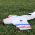
Here is a photo of the “finished” model (is a model ever finished?). Decals are inkjet printed onto clear waterslide decal paper, with white vinyl circles (hand cut with the kitchen scissors!) behind the roundels to cover the yellow of the fuselage. Pleased with the end result as it’s my first balsa model and first EDF. https://youtu.be/p8U8kIKjJ_U1 point
-
Excellent now who will do some early morning shopping for those free garden picnic tables and chairs ?.😈1 point
-
Fantastic first half.1 point
-
Before I tried to cut the EVA I made sure that in doing so it wasn’t going to produce nasty gases! Having confirmed that it’s ok to laser it was then just a case of carrying out a material test to determine the best speed / power combo. Well spotted, it’s a Colchester Student 1800, a lovely bit of kit that I no longer use on a regular basis! There is also an old Myford 7 with tri-lever head that is gathering dust! I really do need to sort out and sell these bits of ‘heavy’ machinery as my metalworking days are over, and for what I need for model building a smaller lathe will suffice!1 point
-
Soldered in and insulated:1 point
-
OK so your part has been anodising for an hour in the acid bath. The items if anodised sucessfully should have a slightly milky appearance when removed from the bath . Now rinse in distilled water and dip into your chosen dye. This should be slightly warm . Too warm and it will start to close the pores in the oxide and prevent the uptake of the dye While it's soaking get an old saucepan with some distilled water on the boil. Many things can be used as a dye , from the expensive purpose made dyes to printer inks , clothes dyes (Rit ) to writing ink. Dylon used to work well but has now changed formula and doesn't appear to work very well. The primary colours apart from yellow work with most dyes but colours vary a lot so a bit of experimenting is needed. Red printer ink produces a very rich pink colour so if a deep proper redis wanted the I found Rit dark red is best. A short soak with Rit dark red will produc a red very similar to Davies Charlton red. Leave it a bit longer and a beautiful deep Ruby red form. I can't emphasise enough that if you want to repeat a specific colou/shade then you really need to experiment with A, type of ali , B time in anodising bath.C,dye used. D temp of and time left in the dye. Also secondary colours like green can be difficult to get to take properly. For instance mixing a nice green from blue and yellow dyes or even using a premixed green dye can result in a beautiful green deposit in the item but when you set ( close the pores) the yellow tends to wash out into the hot sealing bath and leaves a light blue colour with a green tint ! Very frustrating. Dip the part for a few seconds and check to see if dye is taking ok. If it is then the longer you leave it to soak the darker colour you will get. The Frog 150 head was left in the dye for around 20 mins. Different dyes will work at different speeds .For lighter colour just keep checking and remove when happy with colour. Tip, some of the colour will wash out when it's put into the hot sealing bath so let it go slightly darker than your chosen finished shade. When happy remove and place into the pan of hot distilled water and boil for 20 to 30 mins. This closes the pores formed in the oxide layer and seals in the dye .Once sealed allow to cool in the water then remove and polish with dry cloth . Now place in a plastic bag and squirt some wd40 or thin oil and l3ave overnight. The result is worth the wait. You can remove from sealing pan when hot but polish as quickly as possible as a whitish film dries on and can be a so and so to remove. If you get a bit more interested them other tools like a magnetic stirrer can be used to stir the anodising bath . This stops burn marks that can sometimes occur that can ruin a nice finish. It can be a minefield but it very rewarding when it turns out well I'll add some pics of stuff later when the bench is clear.1 point
-
Ok for small planes and long arms,,,😄1 point
-
That would be brilliant leccyflyer.Any Lancaster in the air I think would be a tribute in any event. I know that that at this time is probably a bit early for a reminder but it may give a spur on to those who may be in the final phase of building a Lanc to join in. I am wondering if we could hear the roar of Merlins over the Derbyshire dams this May from the BBMF for this anniversary?1 point
-
I lob mine underarm as your hand moves upwards away from the prop.1 point
-
Steer clear of those and similar types of IDC connectors IMHO. Many years ago they were specified as part of a field modification kit by one of my colleagues who had put together an upgrade outfit for the equipment we were manufacturing. I remember at a meeting, the sight of our senior engineer's face draining of blood when he saw the proposal to use those connectors and his forthright negative opinion of them. He was an ex-Radar man for Cossor and really knew his stuff. I did try them out as an experiment and was also mightily unimpressed - even for simple and non-critical use.1 point
-
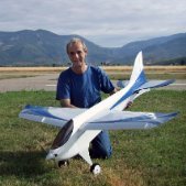
Hi Bill, I normally use 3S but I want to try 4S for the revised Class 2 formula. 3S will fit via the front hatch but 4S won't so I have cut a bottom access. I don't really like the idea from a structural point of view and it limits useful space for the radio installation but I've done it anyway. I messed up a bit by forgetting about the reduction in internal volume from doubling up on foam thickness at the front. I'll make the fuz a bit deeper next time. Lipo Man, that looks funky and fun. Good to hear about the durability, I'm quite confident that mine will be Ok too.1 point
-
The exhaust smell is good to us flyers but after a diesel day the first words my wife's says as I enter the house are " Change clothes and shower !" She loves me really.........I think 😉.1 point
-
That should do fine - foamboard is surprisingly capable surviving flight loads. I’ve got a little fun flyer that was built in a single evening - it’s got about a hundred flights on it so far and looks as good (or more accurately, as scruffy) as the day it was built. All damage is hangar rash from my clutzy handling!1 point
-
Not easy to control but I launch my pusher electrics from the end of the wing like a boomerang, I seen many a fingernail trimmed by pusher props.1 point
-
I agree, the gel filled IDC connectors are very good when used in a static, very rarely disturbed, situation. But sometimes I would use soldered heat shrink joints just to make sure. BTW they are not crimped they are Insulation Displacement Connectors so are not the same as the reliable crimped connectors that are often used. Steve1 point
-
One pass Kev!1 point
-
If it's crimped at the esc, it's breaking, and making, a connection every flight. If it's crimped at the battery, it's breaking, and making, a connection for each flight AND for each charge/discharge/storage. I don't do that with my servo connectors............. Similarly, when I worked on server farm, we didn't disturb any hardware on a regular basis. Each to their own I guess.1 point
-
I've recently discovered I can smell a coconut from a mile away. It's going to come in handy with my new job as a Bounty hunter!1 point
-
First of all its not a silly question, starting out with electric models can be VERY confusing, especially if all things "electric" have always been a bit of a mystery! (Like they were to me). Best bet, is to decide what sort / size of connectors you would like to use (ESC / power lead / battery). Ask any ten modellers which are the best and you'll get ten different answers. After trying a few, all my 20+ models have EC5 plugs and sockets. I buy them by the bag full for next to nothing from e.bay or Aliexpress. Next, get a decent soldering iron, some heat shrink tubing, a small vice and one of those cheap "helping hands" devices with two clips and a magnifying glass. Lots of good videos via Google on how to solder RC connectors. Once you have gathered all the items together, have a play! Like most things, after a bit of practice you will get the hang of it. Good luck and hope this helps you.1 point
-
Then all the servo connectors you have are potential failures as they're all crimped as are all the multiple wires to connectors on gas turbines (and probably the whole aircraft). Crimped connections are, when properly done, more reliable than solder joints which tend to fail where the solder ends. All the PC boards and racks on the first computer I worked on in 1961 were held in place by cold wire wrapped bare tin copper and there were 1000s. They were very reliable and made using a modified Stanley pump action screwdriver 🙂1 point
-
Hi Tim Nice job. Your recent foray into machining has been some of my most entertaining RCM&E breakfast reading these past few months 🙂 The arrival of these wee diesels has prompted me to hunt for the boxed PAW 15 and 1.49 engines in the kit mountain. Found them right away. Also found my engine test stand and Valvespout bottle. What could possibly go wrong? 🙂1 point
-
I've been mucking about with old diesels for a couple of years now. Although, I'm primarily electric powered, there really is something special about starting up a temperamental old engine, and persuading it to drag a suitable model through the skies for a few minutes on a sunny day. All my flying diesels have RC carbs to make life easier - including trying to fabricate an air valve for a DC Merlin, but that's work-in-progress. Tim1 point
-
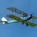
My free flight Beaver had scale position undercarriage and made 3 successive dead straight take offs at the BMFA Nats 2013. It came in 2nd place.1 point
-
A friend wanted a couple of foam model stands made so I reverse engineered the typical EVA ones and did a bit of lasering1 point
-
I would completely ignore the 'Peter Miller / .15 engine' reference in the info panel on the plan, that looks like it was cut and pasted from another plan at the time of publication and never completely changed for this plan. A lot of plans contain errors such as this unfortunately. I think the fuselage sides, from the front at F2 to a fraction behind F4, should have 1/16 balsa sheet on the outside of the 3/16 square frame. This is clearly shown on the cross-section at the F2 position, but there is no mention of it on the fuselage side view. This 1/16 sheet, added to the 3/16" frame, makes the sides 1/4" thick, which is why the lower part of F5 has a 1/4" 'recess'. The 1/8" rear window frame (the one with the curve) will then be aligned with that sloping part of F5 and have its outer face sit flush with this side sheeting. The references 'fill with 3/16" sheet" are for additional pieces of 3/16" balsa filling in the frames in the areas shown around the front and lower half of the fuselage, to provide extra strength in the areas where the engine and undercarriage are mounted. They will make the fuselage sides 1/4" thick in these places. Perhaps the written instructions make mention of this. The plan is rather ambiguous in a few places and some information seems to be missing. Not one for a first-time-builder I think... Brian.1 point