Leaderboard


Popular Content
Showing content with the highest reputation on 28/03/24 in all areas
-
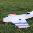
Just completed this and ready for maiden at the weekend as weather looks more promising here in the north east. It is Miss Lizzy, a Peter Miller plan from RCME September 2005. I am surprised how long I have had this squirrelled away, I always liked the look of it as well as the earlier smaller Tequila Sunrise. Since stashing the plan away I have swapped to electric only so I have converted this by making the space between F1 and F3 into a battery bay which has plenty of room for a 3S 5000mAh battery and cut a hatch into the top of the sheeting. Other changes are swapping the u/c to a small carbon fibre unit, 3D printing the cowl and moving the tailplane servos to the rear to offset the battery weight. The pilot and windscreen are also 3D printed. It all comes out to 4lbs 1oz including the battery and with 525W of power it should have good flight performance. ps, I have just gone back and checked Peter's build article (RCME Miss Lizzy build article) for the weight and that states 4lb 1oz, exactly the same as I have achieved with my electric conversion. Just curious if the quoted weight is with or without fuel, mine is in flying condition including the battery weight (13oz).8 points
-
With some decals on.. Panel lines and some weathering to follow as well as the exhaust paintings..6 points
-
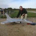
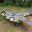
Yep, definitely prefer the razorback version of the Thunderbolt. In fact I prefer the razorback version of everything - P-51B >>>>>> P-51D, Spitfire 1 over any late Mk Spitfires The Thunderbolt has a lot of desireable attributes for an electric warbird - wide track undercarriage, deep fuselage to aid with getting the lipos in close to the front, big radial cowl, so plenty of room for the motor. I wasn't really into them and did question the assertion made several times in RCM&E that the Thunderbolt was the most frequent warbird on the warbird circuit but once I got my Eflite P-47D I was a convert, they fly beautifully and the ground handling is excellent.3 points
-
I haven't dozed off . The Tempest is ready to test fly . Unfortunately , the weather is not playing ball . Neither is the grass patch . Hopefully after Sunday the weather will improve . I probably wont do any more finishing till I can report on the flight .3 points
-
The way to think of using Depron i.e. thin sheet XPS foam, is to consider it as a stressed skin with an internal supporting structure. This internal structure could include carbon rod(s) for extra stiffness. It is likely the resulting structure will be thicker that a simple balsa 'frame' but it can be a streamlined aerofoil to compensate. It is quite possible that a good streamline shape can be twice as thick as a balsa frame structure and still create less drag. It is also likely to be aerodynamically more effective. Fully covering a Depron structure in some way will increase the stiffness but it can add significant weight. How much weight you can save will very much depend on how stiff you want the Depron structure to be. If you use Depron as a single slab structure it is likely to be too flexible even with leading and trailing edge reinforcement. Depron substitution in a load bearing structure is likely to require some experimentation to achieve a weight saving with sufficient strength. As an example the tail plane on my Bombardier Q400. It sits on top of the fin. All 3mm Depron except for the tapered balsa spar flanges are set flush with the Depron skin to give the maximum possible spar stiffness for minimum weight. Not exactly a 'simple' structure but strong enough for its purpose as a twin prop airliner and that includes doing a loop!😮3 points
-
Exhaust details were added. Completed the decals and the panel lines with minimal weathering. May do more when I receive my pencil set. It looks too busy to my eye at this stage. Set the CG at 80mm with 80gr of weight in the box. I still to paint the prop adapter... and seal the paint/weathering with PlastiKote clear sealer...2 points
-
The build of my FW190 progressed well thanks to all who have shared their builds and learnings, especially to Ron for his videos.. Here is a sneak preview. It still requires weathering, panel lines, decals etc.1 point
-
I also added a tail skid to protect the rudder1 point
-
I recently did some research on this and from what I could find BWC can only effect NiCad's, NiMh and PB batteries (not so much in cars but has been found on some farm machinery) but does not affect Lithium batteries due to the way that they work. A bit more here, 5th post down,1 point
-
I'm not sure if it matters whether there is an electrical connection or not since moisture alone may be sufficient to make enough of a circuit to allow the reaction to take place.1 point
-
I would recommend removing batteries from models in storage. If there is no electrical voltage present to drive the electrochemical effect known as black-wire then it can't happen.1 point
-
Our grass is looking rather good, your maintenance team are slipping!1 point
-
Any views on the P47 Thunderbolt ?1 point
-
Some work on the four exhaust outlets. Also the forward part of a hot cowl air escape passage that will exit at the lower underwing oil cooler flap. The Minsi lll colour scheme I am planning has the exhaust outlets unpainted, giving a nice contrast between the dark blue and shiny aluminium. Bit like my Sea Fury. The litho needed a good blow over with a blowtorch to soften it prior to working it into the recess.1 point
-
Much to my amazement my plan to cut the wing centre section in half worked out well, I did cut the main spar before I fixed the top skin in place, as it was very close to the big dowel, I thought it may present a hurdle. Success! Managed to save the dowels, and they slide in and out well, no slop so I am quite happy with the way it has turned out. Made a start on the outer panels That is about as far as I can get now until after the Easter weekend1 point
-
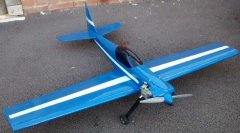
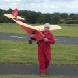
Every year I compete in a daft competition for a three-channel French trainer. It is known as La Coupe Des Barons or the Barons' Cup in English. You are allowed to make alterations to the structure and dimensions of the original model providing that they remain within 10% of the original design. I have two Barons, Boris in Ukrainian markings and Bertie with the British roundels. If I were to crash one shortly before the event then I'd have a reserve aircraft. This actually happened last year! This year I built a new wing for Bertie, using depron for the wing ribs. The completed model is fully 4 ozs (113 grammes) lighter than my Ukrainian Baron which is stock and built from a kit. For the 2025 competition I am thinking of building a new lighter fuselage and tailplane for Bertie using depron for the tailsurfaces in order to save yet more weight. The stock tailplane is made up of 1/4" (6mm) balsa. The model will be powered by a 52 fourstroke because I always compete in the fourstroke class and have given a prize to the leading pilot flying a four-stroke Baron for the last few years. I guess that I am quite famous being the only British entrant and a fourstroke devoté to boot! My question is, "How do you make a tailplane, fin and rudder out of depron sufficiently robust to withstand the flight stresses ofr a Baron in competition when powered by a 52 four-stroke?" Pictures below of the construction of a stock tailplane and the depron wing, and of Bertie and Boris ready for La Coupe. My dog is such a diva that she just had to get into the act!1 point
-
For such a powered model I'm not entirely sure if strong enough Depron tail feathers would save much weight compared to an open balsa structure. I'd be inclined to try a 'solid' Depron (or similar foam) outline, edged with thin balsa for ding resistance. Add more substantial balsa 'posts' at the hinge lines and to give strength and bending stiffness. Don't over do the balsa otherwise you are effectively in-filling the structure with Depron where there was previously thin air, if you follow my meaning. Then cover with brown paper (and PVA) to really ramp up the the torsional and bending stiffness. Cutting lightening holes in the foam would rule out brown paper covering for a more conventional covering material, though I doubt would save much weight. And it may not be as stiff. Brown paper can form a surprisingly stiff edge on a curved leading edge, so thin balsa edging could be omitted if you were striving to save fractions of grammes and you were careful to avoid hangar rash. Here is a picture of the twin fins and rudders for my current EDF model using the foam and brown paper approach. The thicker balsa post on the rudder is because I shall be using a long double sided horn (similar to on a closed loop rudder) to transmit rudder movement on to a vectored thrust unit. Personally, I would happily use this construction for a 52 IC powered model without fear of flutter ruining my day. I'd be happy enough to weigh and measure the areas of my fins to give you an idea.1 point
-
You need continuous cast bar, most of the usual suppliers sell it. M Machine, Noggin end, College etc.1 point
-
I've got loads of Mutunuc 61 and 65,s but until now not a .46. Seemed the 40 and 46 were only available in USA. this one was for sale here, brand new, so I got it.1 point
-
found a spare Mag V in my ST parts.1 point
-
For what it’s worth, I suspect larger than 10x6 would be fine. I spend very little time at full throttle with mine, so proximity to your motor max rating is unlikely to be a problem. Good luck with your maiden - hope it goes smoothly!1 point
-
As a wise man once observed, there are no stupid questions, only stupid answers! It's an easy mistake to make if you are used to connecting the battery to a dedicated slot - although as you probably know, it's only for convenience as the power rails are commoned in the receiver.1 point
-
Here is a mock up of where we are so far, control runs in, fuselage and tail ready for covering probably tomorrow. I want to get on with the wing construction as much as possible before the Easter weekend as the family will be home, guests arriving, which means that I will not be allowed in the garage for the duration! So, the centre section is built first, in one piece then cut in half once skinned. in the article Roy Salter mentions that the wooden dowels inserted as a sort of jig to keep it all lined up are sacrificial and cut in half then disposed of, I dont think that is nessessary so I will save them. First of course I have drawn some templates on some thin ply, the centre section is a constant chord, the smaller rib is the outer one on the wing tips, the intermediate ribs are not shown on the drawing so I will use the sandwich method to produce two (handed) sets. The centre ribs which take the wooden dowels are 1/8th ply, easy to do on the band saw, but I don't know how I managed that on my original model I must have used a fret saw, I really cannot remember! I managed to find enough scrap balsa to make all the balsa ribs, these are the centre section, the rest are 1/8th ply 8off The ply ribs are done, drilling the 12.5mm hole for the beech dowel was a bit tricky and even then the dowel was a very tight fit, so I wrapped some sandaper around the base of a drill and relieved the holes until it was a nice slip fit, I also sanded the dowel with very fine sandaper and then gave it a couple of coats of furniture wax as a form of lubrication, seems to have done the trick. The rest was easy, first laid down the bottom sheeting and cap strips The all the ribs using the dowels as suggested in the Roy Salter article to jig it all together, and also I have fitted the dihedral braces that will slip into the outer panels I have left a small gap between the centre ribs, enough to get a razor saw between them to cut the wing skins once the glue has dried and I have lifted it off the bench. Top skins and cap strips on, I have marked to centre line to guide the razor saw, hold my breath and cut it in half once all the glue has dried overnight1 point
-
I opted for this livery with yellow rudder and cowling.1 point
-
Tail feathers on nice and straight , plus provisional canopy fitted (yours and mine will be clear )1 point
-
Oops! Well spotted! 😄1 point
-
Bit more done to the wing fairings. More later...1 point
-
I've been a bit sidetracked recently with other stuff but have got a bit more done: I decided to make the motor mount/battery box removable in case I decide to fit a sound system at a later date. Next job was to sort the wing mounting. After fitting some m4 bolts into the back of the T-nut, I put some marker pen ink on the ends and then fitted the wing and pressed down to make an imprint. After drilling the holes slightly oversive, I then 3d printed a pair of washers. This allows fine adjustment of the position of the wing by measuring from the tailpost to each wing tip and adjusting until they are the same. The washers are then glued in place. I then made a start on the wing fairings. More later...1 point
-
Yes quite snug Paul, but cam be opened out once the skins are in place and the scale size openings are established. Fuselage went back on the jig to glue in the stab. This has been glassed and cut back smooth already as harder to do later. Epoxy and micro balloon mix on the saddle and two strips of carbon cloth on the inside to reinforce. Lower rear formers and stringers now added. Carbon push rod for elevator in place. Note guide hole in added cross member mid distance, to prevent any bowing when pushing for hard up elevator. At the rear the tail retract was mounted prior to adding stringers to ensure I had the travel to completely hide the wheel. Outer snake guides in place for rudder and tailwheel closed loops. All the above proved very straightforward but the front end between the cowl and the wing leading edge is a different story. Neither of the key 1/4” ply lower formers, although correct to the plan, fit anywhere near to the correct position. I suspect I shall need to remake these parts.1 point
-
Not really a new model but a few weeks ago, while doing a bit of instructing, I failed to take over control of the club's Seagull Boomerang quickly enough when it was a long way off down wind. Both my trainee and I lost orientation and the model hit the deck. The wing on the Boomerang II is fully sheeted and was only cosmetically damaged. Twenty days ago I started the repair with a fuselage ripped open like a banana. Yesterday I flew it again. By my standards that's really quick!1 point
-
Almost there ,just a few to add like fake rigging and a quick dust of satin proofer and the inevitable wait for the weather to co-operate 😕1 point
-
That's the major wing repairs sorted out, just the covering and attaching the ailerons but before I do that there's the issue of the discoloration of the wood to deal with. The natural finish polytex will expose the difference in colour quite starkly, looking around the workshop I found this In the previous picture of the wing tip repair I have applied a coat of the paint and sanded it lightly and I think it gives the appearance of being from one piece of fresh wood? Well it does to my eyes lol ! this is perhaps a better illustration Now back too fitting out the fuselage U/C on,simples! Servos fitted in the same position as it was received in,however with the engine it was nose heavy? The joggle, cheap and effective. Works this end as well So far it's cost £20 for the airframe ,a small amount of wood, paint/fuel proofer and covering that I had to hand1 point
-
If you want to build an all singing and dancing version of the 'sharkface' then this would be the version you want **LINK** The 'sharkfish'.1 point