Leaderboard


Popular Content
Showing content with the highest reputation on 10/06/22 in all areas
-
Some rather dismissive replies on this one it seems. I thought that the purpose of the forum was to offer guidance and advice rather than try to belittle people for asking for it.3 points
-
Thanks for the reassuring comments and advice guys, I'll proceed with a careful set up as per your information and suggestions. I've bee flying R/C for a long time now but really restricted to many years of Thermal and Slope soaring activity. Power flying as such is relatively new to me, hence the slight hesitancy in just going 'full on' with the sticks straight away! The Turbo Timber is something of an indulgence on my part as I usually build from plans and kits. At 78 I need all the help I can muster to keep my confidence and a modest skill level at an acceptable point! I'm fortunate in belonging to a very small group of local fliers who have encouraged me towards putting a propeller on some of my models now. Slopes get steeper and towlines harder to tug these days for me. Take care and best wishes Chris (SW)2 points
-
Quick note: my email address is: [email protected]2 points
-
Here is (some considerable time later!!!) The end result of all that filling and rubbing down, not yet flown but will be very soon ?1 point
-
Dark nights fix-up. ?? 21 months fix-up. ( really 28 years ) Actually a reason for the current delay is building other models. Original cowl had cheeks to hide side mounted (or inverted) motor . There is a fibreglass cowl version available but I'm not paying £23 for one. Not fussed about keeping it authentic. Irvine 53 mounted vertical for ease of operation. Found a canopy in the garage which I maybe acquired for original refurbishment . Not flown yet, still plucking up courage as I'm completely out of practice. [ This is one of my models that I needed wing mount screws for which are obsolete. A couple of guys of the Forum came to my rescue and supplied me with the necessary. Very much appreciated and saved me some hassle ]1 point
-
I resisted going electric for quite some time but eventually I had to admit that the complete lack of fuss, bother and faff was too compelling. I would like to see a few scale models and a multi or two in my future and not having to worry about tuning, cleaning, starting, cutting out, idle issues just takes away so many areas of anxiety for me. In other news, your build here continues to inspire me. That inspiration may take a long time to bear fruit, but nonetheless, reading through this has been an education.1 point
-
Filler primer and added blister to give clearance for the throttle arm..... so that leaves just the radio, fuel tank and control rods and lower wing mounting to sort out1 point
-
Perhaps the next question is which stability option you pick. If you are a beginner then pick the 'stab' mode. This limits the amount of bank/pitch/yaw you can achieve and will return the plane to straight and level if you simply let go of the sticks but for it to achieve this it is important that is set up correctly so the gyro knows exactly what 'straight and level' is. The other mode is 'rate' stability where it slows the rate of change of bank/pitch/yaw but does not limit by how much the plane can deviate. In other words the plane becomes more docile and is less upset by gust turbulence but it remains aerobatic. This mode requires no special set up. If you have access to a suitable 3 position(?) switch it is a good idea to include an 'off' state so you can compare how the plane flies with and without the gyro in operation. It can be very instructive! Finally do not set the gyro sensitivity to more than 50% at least initially. If the sensitivity is too high the gyro compensation can 'over shoot' causing the plane to self oscillate possibly in all 3 planes at once.?1 point
-
On the way to Buxton on the A6 there's a section of road works with the sign "cats' eyes removed" a bit further down the road there's a very good home made sign saying "mice very happy".1 point
-
Fairy snuff Danny. ?1 point
-
That's looking super Gary, great job! Looking forward to a flight report when you can (big SW this weekend btw!)1 point
-
Your logic is correct Skip. Ail 1 Mount as per instructions, Arrow forward on the C of G Mount in a Pre - Trimmed model, or it will work overtime. Set the Gain low to start, about half of the full turn of each pot. Enjoy flying in wind when no one else dare to up!1 point
-
Jon said, and it’s my experience of the 200 FT, that the slow run may need up to a full turn in (leaner) with correspond tweak to top end. So far my 200 FT has about ½ turn and it’s not enough! Going to have a go with the twin 160Vs in the Tigercat on Monday!1 point
-
Air leaks, dirty fuel,poor fuel handling, overheating and running too lean should cover 90% of issues1 point
-
Wot Ron said! Danny, your Saito is a high quality engine with a reputation for reliability. Ok, the exhaust is non-standard but that is not usually an issue with four-strokes in my experience. With two-strokes on the other hand, they are so simple that everything needs to be pretty well spot on before they'll go. I have seen two-stroke engiines fail to start because the glow plug was the wrong heat range or because the fuel was old or otherwise unsuitable. A change of plug and fuel and away they went.1 point
-
Just buy a wire bender and get on with it. Good tools are never wasted.1 point
-
It'll be alright Danny!1 point
-
Slightly surprised by the tuning troubles after changing fuels as i have not experienced anything like it. The tuning is markedly different, but i have not had issues finding it. The new 200i will be set for the new fuel as that it what i ran it on here on the bench. So that is one you do not have to touch beyond the usual tweak to suit the model. Regarding spinner bolts i have had a few let go in recent years and decided to swap all of my other ones out for new ones. I am going to do this every year from now on i think as those spinners arent cheap!1 point
-
Ordered a SLEC ic funfly Tuesday evening saw it was despatched Wednesday morning and arrived with me 11 am today. Quick look in box and well impressed with all sorts of items included and great insruction and pictures Quick coffee and get started1 point
-
There are some good videos on YouTube showing how to make simple wire benders.1 point
-
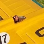
Pushed on today as I was feeling that the build was dragging out, pretty much finished. Glued in the ballast system. Glued in the pilot and fixed the canopy. Painted the jet nozzles. Set the balance point. 1. Ballast and adjustable nose weight arrangement glued in, added a tail of hard 1/8" square balsa so that I could move the battery with the wing fitted. 2. Glued the pilot in, don't look too close! Better than an empty cockpit. 3. Fixed the canopy on with strips of aluminium tape. 4. Masked up for brush painting. 5. Frames added with pre-painted tape strips. 6. Painted the jet nozzles, first silver then a dusting of black. 7. Adapted my Multiplex CG rig by taking the stops and balance weights off to use it as a pivot, I had to move the battery back a fair bit to achieve balance. Weight RTF is 1,860 grammes or 4 lb 2 oz. 8. Pretty much done, might paint on some nav lights and anti-col beacons, I am toying with fitting the sensors to the top of the fins but they could catch in the grass at the slope.1 point
-
So a pleasant evening setting up the radio, and all is good. C of G is about right with 1500mAh 2S LiFe Rx pack balanced on the cowl so should be good. AUW ready to fly, minus fuel. 4.38kg or 9.66lbs Pretty pleased with that......means the model is eligible for light scale Cheers Danny1 point
-
It does show the Bishops who, I believe, are heavily involved in the running of the Weston Park show.1 point
-
But that’s not Weston though is it, tarmac and a control tower. Weston’s just a big park.1 point
-
I know this is out of order but I didn't do a shot of the wood kit which is bulging and good value for just under £300. It's a while ago but I think it was £279 from Sarik as a short kit including plan, canopy, and extra wood pack. Unlike the Flamingo wood pack this one has cut outs in 6mm for the gull wing supports which is very helpful. No cut out however for the aileron spar or the false leading edges. People spend hours watching YouTube videos of unboxing kits. Personally I would rather watch paint dry. So if it turns you on then here is a bit of kit porn. I also have a copy of the story when it appeared in RCM&E as a free plan which helps a lot. I am going to scan it in and can send it to anyone who needs it. Just PM me. Don't overreact when you see this now.1 point
-
Spent all day designing and making the movable battery and ballast system, it's fun 'winging it'! One day soon I would like to design and build a simple slope soaring glider, something I've never done. 1. The movable battery clamp is built on a piece of hard balsa sheet that came with the kit, it will fix to the ply reinforcements inside the fuselage and also be bonded to the floor of the plastic moulding. I had a sheet of unidentified hard wood in my scraps box, I think it is Obechi. Using that I made two 'runners' and a clamp. I drilled for, and epoxied in, two M3 brass inserts to take machine screws. I use these instead of self-tappers on cowlings as they are much more durable. I added a 2 mm scrap of Liteply to fill the gap between the clamp and the battery strip, the gap was 1.8 mm so this was 0.2 mm too thick. I did think of adding a square of sandpaper to the packer to help the grip but it wasn't needed. 2. With the screws lightly nipped the strip is secure, marvellous! 3. Part B of the project was to work out how to fix the ballast bar, I started with some very hard balsa rails to locate it fore and aft. I also cut slots for Velcro straps, I use a lot of these, even replacing cable ties on my motorbikes as they are kinder on the paintwork. 4. The whole system. I will have to add an extension to the rear of the strip as all this will be under the wing and not easily adjustable. My plan is to leave the clamp just slightly loose so I can move things then tighten fully to lock it. Another thought is that the battery will need some foam top and bottom to fix it vertically in the nose otherwise it will swing like a bell clapper. 5. I then realised that the cross rails would stop the battery strip from being removed so I cut the centre parts of the rails out. 6. There is room for a second ballast bar and it would also be possible to stack it over the first one. 7. I kept thinking how odd the CG position given in the instructions was as I have almost always used the leading edge at the root for full-size weighings and models. It struck me that if I joined the two leading edge marks with a straight edge or piece of string that it would give a position at the roots, the two pencils are pointing at them. It's something like 190 mm aft of the datum (leading edge at the root) but will confirm that when it's next assembled.1 point
-
Did some pilot shopping this morning and found one that looked perfect but I backed out as it was from the EU with warnings of Fed Ex charges for collecting VAT etc. Made, fitted and painted the Plasticard covers for the tail pieces of the fuselage. Fitted an on/off switch and volt checker, both accessible through the open jet pipes. I have telemetry on my transmitter for Rx voltage but I do like to see old school coloured lights as well! Went searching for foam to pack out the nose to place the battery, apart from not finding any foam I thought this would be fiddly and an imprecise way of doing it when I remembered that I used to set CG position on an F5J glider by mounting the flight battery on a stick so that it could be moved fore and aft. I found the stick (just a thin strip of ply with Velcro) and also the glider ballast weights, a combination of brass and aluminium threaded rods. So...I have a battery on a stick now and just need to work out how to make it adjustable, at the same time I will make a ballast mount. 1. This open area is to be filled with Plasticard. 2. Like this... 3. I sprayed the aerosol paint into a used yoghurt pot (a clean one!) and used a brush to touch in. 4. Looking at the radio gear, the receiver will be fixed where it is. 5. An on/off switch and volt checker. 6. The ballast system and battery stick from my NAN Xplorer 4000, the holes in the end of the aluminium pieces allow the ballast to be placed optimally for CG. 7. The Xplorer 4000 (4 metre span) for interest, luckily the wings de-rig into three pieces for transport! I have 3.5 and 3.8 metre versions of this glider. 8. I made a Liteply stick for the battery and need to work out how to vary the fore and aft position and fix it, pencil behind the ear time!!1 point
-
Well for a change I have started with the wings. As you can see in this picture the ribs towards the tip have no backs on to make way for the aileron spar and separate inset aileron. The problem was, how do I make sure they are all lined up with each other to take the dummy leading edge and aileron spar. I used a cut off piece of 3mm square to rest on the top and the engineer square to line them up. I used CA and acclerator to make sure they stuck fast all the way along the wing. This shows the whole left wing which was really quick with CA. Once this is dry it will be jacked up on the wing supports - watch this space. One omits R2 in order to make way for the ply wing joiner box supports. Once the brass box is inserted coming out through R1 one closes it with ply and webbing for support. At the bottom of the picture you can see that in order to get the inboard ribs to lie flat, the trailing edge has to be packed up by 9mm - a piece of 6mm and another of 3mm which will be removed when the wing comes off the board soon.1 point
-
A bit chilly outside today so I pottered in the kitchen. Ailerons and elevators fixed, radio set up with some initial travels. A few more graphics added. Looks like I will be able to set the balance point just by moving the battery, at the moment a four-cell NiMh pack under the cockpit is working. 1. Quite an awkward thing to balance, pencils taped to tins works, 300 mm along the leading edge from the wing glove for the glider version, 230 mm for the power version. 2. Battery under the pilot should be about right.1 point
-
The weather was ok today to do more spraying in the garden, I finished off the grey and added some silver near the jet pipes. A lot of masking, my main worry was over spraying the graphics on the fin and paint lifting with the masking tape, luckily neither happened. Jobs left to do now are: Hinge the ailerons and elevators. Make and fit Plasticard covers over elevator servos. Fit the cockpit parts and find a pilot. Fit the canopy. Add tabs to the upper wing glove strips Paint the jet pipes. Add the remaining graphics. Add receiver and battery, set balance point. Range test, fly. Photos: 1. I used the wing and top hatch to mask off the insides of the fuselage and carefully masked the fins. 2. Sprayed and dried quite quickly. 3. Flipped upside down to paint the bottom. 4. Going well so far, just a few greenflies decided to visit and get stuck. 5. There are bare metal sections of the fuselage for the hot zones of the engines, I found some alloy wheel silver that I use to paint the final drive of my motorbike. I read the label and it said it contained acetone so I tried it on a bare piece of plastic first in case there was any reaction, no problem. 6. The problem with masking is that you don't find out that you've missed a bit until you take it off! 7. Came out better than I expected! 8. Same deal with the top hatch. I have Tamiya masking tape but standard DIY tape worked well. 9. All good. 10. Very happy that the graphics didn't get over sprayed and there is no hard line where it was masked. 11. Light at the end of the tunnel!1 point
-
Added some more decoration. Moved CoG back by 25mm so should not need so much up trim but still suspicious of my tail incidence. Weighs circa 1kg, flew with 300g ballast added and weight fine for our hills. Will take max 550g ballast. Will take it up hill on Sunday weather permitting ?1 point
-
Suspect above is rather old hat to PSS folk, but I got quite excited lol1 point
-
Use the transfer stuff to assemble decal: Peel off on transfer stuff, apply, and remove transfer stuf ?1 point
-
Decided to have a go at using a vinyl cutter for the decals. Alignment with transfer tape and star registration marks went surprisingly well so thought I'd post some photos here for anyone who was thinking of doing similar. 1. Create or find SVG shapes, and add some registration marks (stars here) 2. Load into design tool with each colour on separate layer. 3. Send to cutter and then peel unwanted stuff off Cover with transfer stuff:1 point
-
Some more progress today. Finished trimming the wing gloves and glued them on. Glued the left fin on, will leave it to set overnight. 1. There is small gap in places between the wing gloves and fuselage, I've wiped in a fillet of aliphatic resin. 2. More wing glove fixing. 3. Made some simple jigs for alignment of the fins, might look like an extravagant waste of highly valuable balsa but woodworm had been busy on this piece!1 point
-
Video by friend to prove it flew ? It's a speck except for take off and landing as I was reluctant to fly close in on maiden. Fears about +ve tail incidence may have been well-founded as it needed a lot of up-trim. But CoG is 3/4inch too far forward, so will shift this back and program in both ailerons up on an extra trim switch as suspect RG15 TE is not helping any.1 point
-
Time to stop for today, the wing gloves need trims in various directions and I don't want to cut or file too much off accidentally. Weight now is 1570 grammes (3lb 7 oz) minus torque rods, receiver and battery and some small bits and pieces. 1. Looking at the wing glove fit, a trim of the wing slot moves the tailplane and fin slots, a trim of the tailplane slot moves the wing and fin slots (etc, etc, etc!!) 2. Needed a little trim behind the wing to allow the aileron torque rods to pass, same trim both sides. 3. I cut the upper part of the gloves off where it passes over the wing, I was trying to avoid this to save a joint but it was necessary. 4. The cut out parts will have tabs each end, Velcro is provided in the kit to hold them on. As the model will fit easily in my car in one piece I might tape the panel joints and edges on final assembly. 5. The top hatch appears to have warped upwards since moulding, I tried weighting it down over a few days which didn't work. Might try some gentle heat, experimenting on some scrap plastic first. 6. The ailerons have been left slightly oversize in span, once the wing gloves are fixed I can trim them to give clearance at both ends then cover them. I've just wedged them in here. 7. Getting there slowly. The fins are just dropped in and leaning towards each other as the wing gloves have to move inboard slightly yet.1 point
-
A map with contours may give a better idea as to the lay of the land... Slope soaring is great, out in the fresh air and usually involve some excercise. Enjoy.1 point
-
She flew today. Took off straight as a die and needed just 3 clicks of down. Sadly, a radio problem meant a forced landing which ripped the retracts out. Easily fixed though...1 point
-
Gyroo, RIchard Harris plan from RCM&E April 20221 point
-
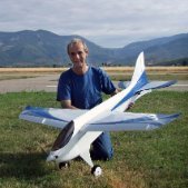
Laydeeez and Genulmen, I give you.... Regianne RE2005 The latest product from the G Davies/ E Robson/ R Wills skunkworks, a foamboard scratch build. Built using a mix of FliteTest Maker Foam and Hobby craft foam board with a small amount of ply, lightply and balsa. It's a full-fat flaps and retracts warbird at 55" span.I had hoped to fly it on my little 2200 3S packs, but I've been guilty of a heavy back end, which is a repeating theme in my life... Had I got away with the 3S packs, it would have been 3lb 10 Oz ready to fly. Sadly, I will need to use big 4S packs to get the thing to balance, so will now tip the scales just over 4lb. Hardly porky though. Some scale liberties have been taken with the undercarriage position in order to make a practical model. Our strip is bumpy and doesn't suit tall, narrow undercarriages. The positions are cribbed directly from My (originally Peter's) Ballerina. That copes perfectly with the strip, so is a great role (roll) model. It's covered in brown paper and PVA, although the tail feathers are not covered at all, just painted directly onto the hobbycraft board. It's then sprayed with watered down emulsion paint. It's a really cheap build. I reckon the material cost in the finished and painted airframe is no more than £25. If I can satisfy myself that everything is ok, I will maiden her tomorrow... Graham1 point
-
You could always drill more holes in the right side of the bell tank, move the rudder connections in and the servo connector out.1 point
-
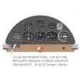
Hello Greame Poke, I drew my own plans based on a 3-view by R.S.Hirsch. I could send you a copy of this 3-view if scratch-building is no problem for you. Karl-Georg1 point
-
David, I think they're called "torque rod control horns".1 point
-
My Miles Magister maidened 1stMay. Full build here and there is a thread here.1 point
-
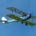
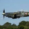
Club mate Mick King test flew his De Havilland 71 Tiger Moth yesterday1 point
-
Its not the mid 80's any more ?1 point
-
1 point


.thumb.jpg.6e9ca6f431386c6c58ab30794f332751.jpg)