Leaderboard


.thumb.jpg.6e9ca6f431386c6c58ab30794f332751.jpg)
Popular Content
Showing content with the highest reputation on 28/12/22 in all areas
-
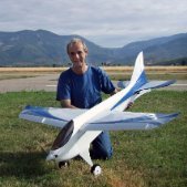
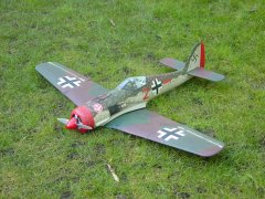
Time for an update! All RC funktions are working. Last job was rudder linkage. With the main wheels far from the COG there is some force on the tail wheel, maybe I have to add a spring to the linkage. Today I made the first test run on the street in front of our house. Motors are running very smooth at all power settings, although without spinners. Full power is amazing. Sound is really good with the Scorpion motors and Aeronaut props and thrust is plenty. Another important check was for COG position. With all equipment necessary for first flight and the 6S5000s in forward position I am on spot, which is a great relief. COG is shifting backwards 5-8 mm when wheels are up, so I have to care for that. Weight with spinners is exactly 7 kg, which is fine for 235 cm wing span. But the wing area of the Whirlwind is not much more than for the Spitfire. Missing details and colours should add another 500 grams so with 7.5 kg I am at 110 g/dm², which is fine for that model size. Timo4 points
-
Christmas is the time for goodwill to all men.....and pilot painting. Have decided that he shall be called "Reg" which seems suitably 1940's.2 points
-
For scale fidelity ‘B’ would get my vote although ‘C’ is probably most common with Cub model designs, - easier to build with a flat bottomed section. 👍 Full size practice is often to design a wingtip to minimise drag and maximise efficiency. Its shape will not have an effect on adverse stalling charactistics. If a designer is concerned about that he might include a little washout, amongst other things. A properly constructed parallel chord wing on a lightly loaded Ben Buckle Super Cub should have a totally benign stall - unless severely provoked! Just build it to the plan, don’t agonise about it. 😉2 points
-
I’ve flown a Goldberg Cub, and the 26% Toni Clarke PA 18 Cub. Both are benign flyers. Neither had washout. I reckon you are making work if you want to alter the aerodynamics of an established kit/plan. And don’t think it’s an easy fix. A wing designed to be warped is made floppy. A wing designed not to be warped is built to have resistance to the warp. Anything will tip stall, bank it, reduce power, keep raising the nose, or trying to raise the nose with the elevator, and nothing will fail to tip stall. Try it at night, and don’t go there thereafter.2 points
-
A cracker for Christmas Eve. This is Geoff's super scale F4U Corsair. The sound is just gorgeous...and the slow fly bys perfect for the camera. Happy Christmas folks !2 points
-
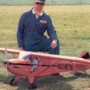
A shot I took way back in the summer during a special weekend that the club held.1 point
-
Ambassador Spock Given you are new to electric RC I actually applaud your decision to adopt the Spektrum smart battery technology to avoid some of the pit falls with LiPo technology but as you have noted it does rather tie you into their proprietary batteries as well as to a degree having to rely on a chip built into them. Just remember there is a lot of energy stored in a LiPo, more then enough to ignite their flammable contents into a runaway condition if things go wrong. Treat all LiPo with caution and do not abuse them in any way. Do feel free to ask any questions about anything to do with the hobby. Experience and advice are things this web site is not short of!1 point
-
To eliminate whether it is a card problem dowload a model from the DX8 and then reimport it, if that works it isn't a card problem.1 point
-
Thanks for the comments. An actual Seagull, as with many birds, needs no fin but then it does have 'stabilised' variable geometry and incidence wings along with a variable area and incidence tail. I wish! To use an RC plane type stabiliser you have to separate the control into separate roll, pitch and yaw functions which almost by definition means an adjustable fin or some form of wing drag brakes. I have gyro stabilised planes than use no rudder function but they do have big fins to ensure natural yaw stability. I was specifically avoiding using a gyro simply because the Plane Print version manages without one although it is in effect a flying wing using the accurately controlled wing profiles, sections and incidences possible with 3D printing. What I am aiming for is a configuration that is stable (just) in pitch and yaw without relying on the specific wing aerodynamics of a flying wing and at the same time keeping within my 250g weight limit. Of course mid winter in the UK is not an ideal time to test it but it is getting closer!1 point
-
80mm opposed to 70mm from the LE means less weight would be required. The manual states that no additional weight is required to get the correct balance point. Have you got the LiPo battery as far forward as it can possibly go? A few of my club mates have had these (and the foam Acro Wot) and none have mentioned any problems with their models. Brian.1 point
-
Cellulose thinners are just as dangerous as petrol ! I hope you did that outside ?1 point
-
The fin and rudder seemed to be fairly simple to progress; not a lot of material required and all was to hand. Photos of the Vega Gull show that it was produced with a straight leading edge to the rudder as well as with an aerodynamic balance. Some also had a shrouded hinge line, some with exposed hinges. Perhaps the prospective owners could specify what they wanted and were prepared to pay extra for. Being a glutton for punishment I decided that the aerodynamic balanced rudder and shrouded hinges would be worth the additional work to obtain a smoother finish to the control surfaces. It was also the option that was on VP-KCC, Beryl Markham’s record-breaking aircraft, which I believe I’ve settled on for the finish – that’s a long way off but might as well build in the options now. The fin & rudder ribs weren't computer drawn, but French curves are pretty useful when it comes to reproducing diminishing sections. I started out using 2mm tufnol for the hinges, then decided that 2mm was too heavy and as there wasn’t any 1.5 or 1.6mm tufnol lying around, 1/8 ply would work just as well and offer a small reduction in weight. The dual pivot sits in the fin tail post and the single (rounded) pivot sits in the rudder tail post. A 1.6mm diameter length of piano wire hinge runs up from the bottom of the rudder through a plastic tube, to act as a guide, and will then be retained by a solder tag screwed to the chamfered part of the rudder. Having the rudder detachable primarily aids getting the bits painted but will also help with storage as my hangar is a wooden shed with a pitched roof. The internal height at the eaves is 80” so with the rudder removed the model should be able to just about stand upright – it’s getting congested in there. I’m reliably informed that the ideal number of aircraft to own is always dictated by the size of the shoehorn. The tailplane will have a similar shrouded arrangement for the elevators, although I've not go to that stage yet. The curved tips have been laminated with 1/32 ply between 1/8th balsa. The ply is there to offer a bit of protection from the inevitable hangar rash. With the basic bits coming on, I couldn't resist getting a picture of the parts assembled. Beginning to look like an aeroplane. Unlikely to fly the Atlantic but I can pretend!1 point
-
Recent press reports said that 60% of mail is still undelivered. Oh! Nearly forgot they're striking for more money. Perhaps they would get more respect if performance was better.1 point
-
Cleaver, creative, inspirational = stunning results 👏1 point
-
That's a well written article. You should be proud of it. I've downloaded and saved it even though I'm quite well-versed in electric flight technicalities. I seem to recall the esteemed BEB suggested the starting point for designing a power train was the propeller and how fast you wanted it to turn. That really helps when converting from ic to electric propulsion because the prop doesn't 'know' what's driving it 🙂 One minor quibble is your quotation of Ohms Law - Watts = Amps x Volts (which is, of course, correct). In fact Ohms Law relates Current(I), Voltage and Resistance (V= I R) and the various power equations are derived directly from that.1 point
-
Thanks RW- I'm looking it up now. Looked it up- excellent- extremely comprehensive!1 point
-
I wrote a booklet on the Basics of Electric Flight which can be downloaded from our Club website. The link is here:- https://dmfc.org.uk/downloads/electricFlight.pdf1 point
-
No,,,if they are made for 4.5 volts, it's like a car, mine is limited at 250 klm/h but I don't have to drive around at that speed;,,,,, Thank's Matty,,,,1 point
-
You are not being forced to use Spektrum, so you are fee to go and do what you want. What Spektrum are doing is removing some of the possibility getting its wrong and causing injury or fire (plugging bullet connectors together). They no doubt would like to be dominant and dictate to the global market of RC, but with other platforms and open systems available that is very unlikely. Spektrum have tried collaborating with model manufactures, but even then you can still buy the model without the Spektrum RX so it stands to reason that even they know sales of non RX models must be significant or they would not do it. I would like to see someone plug an XT 60 incorrectly together, but as a friend said once "nothing is fool proof to the most ingenious idiot" To this day I can't understand why TX/RX manufacturers don't all do some form of model match.....the number of times I see people power up an electric model and then announce they have the wrong model selected in the TX...Fortunately the clubs I belong to carry out pre maiden checks with covers throttle cut/loss of signal, but then don't get me on the unrestrained electric model debate. 4Max has good advice for their products and should I need detailed technical information then I would give George a call and place an order, if its just a lipo for general use then GNB will do the job. If I wanted hassle free then a Spektrum battery is available. Try asking Spektrum? If its SMART then perhaps the discharge is managed based on pack temperature and some other factors? If you are relying on product to "manage" then just be happy its knows what its doing. Take advantage of the faster charging if it suits you or adjust to your preferences or that of "general" advice (anything that is not pressed to its limit will last longer) Nothing to add that already has been said If you have a fire "resistant" bag then it would be good practice and probably convenient to store the batteries in the bag/bags. Always so much fun getting to the flying field and remembering where you left the wing tube, batteries/battery adaptor etc...1 point
-
Another vote for e-calc, but there's also drivecalc.de which is free.1 point
-
They probably do know more than most of us. But the cynic in me says they want to lock you into their own world, where you have no choice but to continue buying their products, and theirs alone. Then they have total control over pricing and profit. P.S. I'm not a Spektrum hater - I've had several of their transmitters, and still use a number of their receivers.1 point
-
The piper cub wing is a lot like the Baron, the same section etc,,, I have never stalled a wing that shape. If you want a plane that will tip stall build a Spitfire with it's beautiful elliptique wing and over power it with a big 4 stroke and an oversized APC prop,,,1 point
-
I don't have the Ben Buckle version, but I have had several cubs over the years. RM plan version 1970s ( 72") ThunderTiger J3 cub ARTF (80"), E -FLITE (67") and the big H9 ARTF 9 (108"). None of these had washout and none of them were prone to tip stalling. So it may not be much of a problem with the BB version as long as the model isn't too heavy?1 point
-
So, I've spent a few hours pottering with some electric retracts using my Radiomaster TX16 with EdgeTX, and a servo tester. Firstly, with the servo tester: with the knob fully rotated one way, the retract is in fully up; gradually rotating the knob has no effect; when the knob is rotated as far as it can go, the retract comes fully down. Rotating in the opposite direction has no effect until it reaches it's limit. The retract moving from fully up to fully down, or vice versa, takes under a second. The conclusion is that only the extreme outputs (-100 and +100) have any effect and the proportional channel is behaving as a switch. I then set a two-position switch to activate the retracts. Up position (-100 output) made them fully up, and Down (+100) made them move to fully down. Again, the retract moving from fully up to fully down, or vice versa, takes under a second. No point in adding a curve; adding 'Slow' values has no effect as the output is either -100 or +100 instantly; adding Delay does not slow the operation of the retracts, just delays when they start to move. I then plugged the retract into a receiver on Channel 1, mapped to the elevator control. Full down on the stick (an indicated output of -100) moves the retract to fully up; full up on the stick (+100) moves the retract to fully down. The proportional channel is behaving as a switch. I can add a curve so that a mid stick position is -100 or +100 and when the stick creates the -100/+100 position, the retracts activate; only -100 and +100 have any impact - the proportional channel is acting as a switch, but I do not need to use full movement of the stick. I added a 'Slow' value of 5 seconds and it has no effect - as soon as the output hits -100 or +100 the retract operates and takes under a second to fully deploy. Delay does exactly what it says - you hit +/-100 and after the delay value, the retract operates; once it starts, it takes under a second to fully deploy. So..... in my experience, nothing we do at the transmitter effects the actual speed of deployment of electric retracts. We can delay one or either leg so it looks more realistic, but the speed at which the retracts actually come up or down once they start, is fixed. Maybe more expensive retracts are different.....1 point
-
Really impressive building Phil, you do make some wonderful shapes with Correx, its mind blowing - I will keep on at you for your first Balsa build but I must admit I cant wait to see your new bigger Super Cosair up close! Great work on the vac form canopy btw - impressive again!!1 point
-
Once I had finalised construction of the cockpit cut-out I used a bit more filler to close off any exposed flutes and then moved onto the canopy. For standard sized Correx builds it’s generally possible to create a canopy from one or sometimes two 2 litre pop bottles. For this scaled-up version that was not going to be possible but fortunately I managed to find some 3 litre lemonade bottles that were just about large enough. I made a few Correx templates for reference and then carved some previously glued together blocks of wood to shape. Once I thought I had the shape about right I then tried to mould a single 3 litre bottle over it, which failed miserably. Ultimately the bottle wasn’t long enough plus I was unable to shrink the ends down sufficiently before it overheated and turned white. For the second attempt I chose to make the canopy in two pieces with an overlap joint where the canopy frame would be and this proved to be far more successful. With the two halves glued together using canopy glue I then used a series of tiny self-tapping screws to secure it place. Having done all this, a few days later I then looked at it afresh and decided the rear section of the canopy was too bulbous so went on to modify my wooden block and mould a more teardrop shaped version in its place. This looked a little more representative of the real thing so I then went on to paint the frame. Finding photographic images of the cockpit detail of this particular aircraft remains a challenge since sadly both the plane and its pilot were lost in a crash in 2012. It seems many features of the cockpit area in particular were unique to this aircraft so I am having to use a bit of licence in guessing what some of those features actually looked like. The rear stays for the pilot seat aren’t too much of a problem so I’ve created those from some offcuts of carbon and aluminium. Detail of what’s happening behind the pilots seat is a little more sketchy though so I’ve created my interpretation of it using carbon rod, some plastic sheet, heatshrink, electrical wire, a nylon spacer and some tin. The only photo I’ve managed to find of the cockpit instruments themselves is this 360 degree panoramic one by Moose Peterson, plus there is some in-cockpit video footage too so I have yet to see what I can come up with in the way of a photographic image of the instruments at least… I am using a David Banks pilot figure – beautifully modelled by David and super lightweight too. He is only a bust figure so my cockpit is quite shallow in depth to suit. I’ve got him mostly painted now with just a little more detail to add. For the plane my plan is to spray paint the blue and the white chequerboard and stripes, then use white self-adhesive vinyl for the text and numbers but I am holding off from doing that until we have some warmer weather. So for the time being everything is now on hold. Roll on the warmer weather! Phil1 point
-
I’m more than a bit late to this party I know but I discovered this Correx build thread the other day and seeing as I can’t seem to stop building in Correx myself I thought I’d post up some photos of my previous builds along with the one I’m on with currently (build number 16!) I started off in early 2019, like many by building the much tried and tested Mig, followed by the A10, Reno Racer Super Corsair, Red Arrows Hawk and then another Mig to replace my first one which suffered one too many heavy ‘landings’. I then went on to modify some balsa plans to make a Mosquito followed by three L39s (part of a group of six in total), a Silver Falcons Pilatus PC-7, a pair of Hawks in the 2010 colour scheme, the Rolls-Royce Spitfire and then most recently 2 more Hawks for a fellow flier. Of all the builds it has been my Red Arrows Hawk and the Super Corsair that have seen most action, some of you may well have seen them and indeed some of the others at the Orme over the last couple of years. I’ve always loved the look of my Super Corsair and it was one that flew well right from its maiden. It’s had a few bumps and scrapes since and there are a few improvements I wanted to make too so I decided this Winter was the time to build myself a new one, still in the same Reno Racer colour scheme of aircraft NX5577N but BIGGER and hopefully better. Initially my intention had been to build something more scale in balsa this Winter but I’m still relatively new to rc flying so I thought I’d give it another year before doing that and hopefully allow my flying skills to improve a bit more in the meantime. My new Super Corsair will be a 120% version of my current one, making it close to 1/8 scale with a clipped wingspan of 62”. At this size it is just possible to cut the wings and fuselage from 4’x2’ Correx sheets. Finished weight is going to be in the region of 3kg (with around 500g of that being nose ballast). For strength the wings will be made from 3mm Correx rather than the usual 2mm. The ailerons are double thickness rather than the usual single piece of 3mm Correx, both for strength and to blend more smoothly with the wing. I’m introducing a rudder in addition to the standard aileron/elevator set-up. All exposed flutes will be sealed with either balsa, 1mm ply or filler to improve the look and hopefully performance too. The wing will be secured with wing bolts rather than rubber bands. All the tail surfaces will be made from two thicknesses of 3mm Correx rather than one and additional bracing and formers will be introduced to increase rigidity of the tail – a weak point of my current Super Corsair as one or two noted on its last flight from the South slope of the Orme, admittedly when the wind speed was well over 40mph! I’ll add as much extra scale (ish) detail as I’m able along the way. This isn’t a full photographic record of a Correx build since much of that has been covered many times already so I’ll concentrate on the things I’ve chosen to do a little differently, for better or worse! Firstly though, some notes on sourcing Correx. Like everything it seems to be getting more and more expensive and tricky to source. Ideally you want to find somewhere local to you where you can pick it up directly because delivery can be both tricky and expensive. If you can get hold of 8’x4’ sheets then that allows you more scope to build bigger but generally 4’x2’ or 4’x3’ sheets work well provided the flute direction runs along the 4’ length, plus they should hopefully then also fit in your car. If you’re having it delivered then make sure it will be delivered flat as many places will either roll or fold it rendering it useless, particularly so with the thinner 2mm sheets. Standard Correx builds generally use 2mm thickness for the wings and then 3mm for everything else. Some time ago I also sourced some non-Correx brand 2.5mm thickness sheet which I have used on many of my wings in lieu of the 2mm and will be using again on this build for my ailerons. The suppliers I have used most recently are:- 2mm Correx:- Kite Packaging 2.5mm Non-Correx brand sheet:- The Plastic Shop 3mm Correx:- K&M Wholesale Suppliers And so to the build itself:- Due to the number of photos I'll spread this over a few separate posts... For greater strength I opted to make the wing from 3mm Correx rather than 2mm. Standard practice is for the aileron to be produced from a single piece of 3mm Correx as well with one flute cut away to make the hinge. This results in a step between the aileron and both the upper and lower surfaces of the wing as per the diagram below. Over time I have also found the aileron is prone to distorting so for my build I have chosen to effectively cut most of the 3mm aileron away leaving just a stub which I have then sandwiched between a folded length of 2.5mm sheet forming a new and more robust aileron. This aileron then transitions more smoothly from the upper and lower wing surfaces. In theory 3mm Correx should have provided a fully flush transition between the wing and aileron surfaces but I opted to use 2.5mm instead, favouring a slight waterfall effect rather than running the potential risk of an into wind step. I glued a few balsa webs within the aileron for support, one of which also serves to strengthen the control horn mounting area. Once folded, I closed the exposed ends off with 1mm ply or balsa as felt appropriate. The wing spar is made from 9mm ply pinned and glued at the crank points and I have then glued and screwed a block of wood in place to support the front wing mounting tab. I allowed for a spacer under the mounting tab in order to provide some adjustment on final assembly with the fuselage. Ply servo mounts were glued to the spar and wing lower surface followed by a bead of hot glue for extra security before fitting the servos. The four sections of upper wing were folded in the normal manner. The exposed flutes on the wing tip leading edges were then cut away and some balsa strip introduced and sanded to shape, followed by some 3mm ply for the wing tip itself and 1mm ply for the trailing edge part. A balsa strip was also introduced to close off the exposed flutes of the wing upper surface along the aileron hinge line as shown in the last photo above. With the wing nearing completion I felt a photo comparison with the standard wing was in order. Although it IS only 20% bigger it somehow looks more like 50% in the photo! Note that I also chose to reduce the aileron length this time in order to make them look a little more scale in appearance. No flaps though – they looked like being way too complicated! I closed the rest of the wing trailing edge flutes off with 1mm ply, I’m not expecting any aerodynamic gains here but to my eyes it will at least look better. And then to tidy things up I then glued a couple more pieces of Correx over the previously open upper surfaces of the wing, leaving a small slot for the servo wires to exit from. Continued in next post...1 point
-
Unless you want to see through the structure try using the matt laminating film. This looks very much like doped tissue and shows the wood beneath but is not atall clear. Below are some parts of a Elf Bipe I have covered . This is 70 micron matt laminating film. Still a lot lighter than Solar tex but heavier some films.f Paint really does adhere well as the matt surface allow paint to get a grip . I have a couple of test pieces made two or three years ago and one piece having been left in a green house all that time . No degrading , loosening or paint flaking. Its also fuel proof and overlapped covering is almost impossible to undo without plenty of heat. Paint can crack if applied to thickly irrespective of what it's aplied to or how it's keyed. A plasticiser for solvent based acrylic can be bought from car paint factors. You could also try a few drops of castor oil mixed into paint before application will keep paint flexible. Test gor quantity to add before committing to paint entire model. It does slow the curing of paint. We used it when making transfers years ago mixing castor in with the dope . I think its also used in Banana oil to keep it flexible. For water based Acrylics or emulsion I don't know what will prevent cracking or flaking although the vinyl silk type does stay reasonably flexible , again depending on how thick its applied. Ps Eagle eyed builders will notice that I have forgotten the mounts for the wing struts so will have to either patch or recover the tops of the wings once sorted.1 point
-
If a Cub is tip stalling likely a wing warp. However if an aircraft is in a turn at slow speed even a cub can tip stall.1 point
-
I'm really chuffed! I assembled the Ender 3 yesterday evening, re-assembled it correctly this afternoon 🤔, then printed off the little dog statuette that's on the SD card that came with it. The quality is much better than that of other 3D-printed things I've bought on the internet, presumably something to do with the slicing settings. The supplied PLA was just enough for the dog -- less than 1cm left sticking out of the feeder.1 point
-
Cracked it! Thank you so much. I followed Roger's instructions but for a moment got stuck at the last paragraph because I couldn't find any 'mirror' option in the move/copy submenu. But I found that after I'd specified the distance to move/copy, the copy had X, Y, and Z axes superimposed on it, one of which I was able to 'grab' and rotate the copy by 180 degrees. I then combined the result. So one more skill learned, but so many to go . . . .1 point
-
1. Construct a plane running vertically near the middle of one of the cones. Do this from the construction menu, and use the offset plane option. 2. create a sketch on the new plane. 3. Project the edge created by the intersection of the cones. Choose the edge that is not visible in your view above. This will produce a parabola shape in your sketch. 4. add a line joining the ends of the parabola to create a profile and finish the sketch. 5. extrude the profile far enough to form a solid through the intersection of the two cones. 6. Use the combine tool, selecting the cut option, using the new solid to cut the cones. there are numerous ways to accomplish this. But this is the easiest way I could think to describe. Although it sounds long and convoluted it is all straight forward. Roger1 point
-
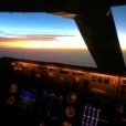
And then it was my turn to fly it FPV ! Excited but a little nervous...1 point
-
Added head tracked FPV to the OMP Decathlon. Was easier than I thought it would be...1 point