Leaderboard

(2020_03_2622_00_27UTC).thumb.gif.375a6ebc5cd681eb724c62879a10ef8d.gif)


Popular Content
Showing content with the highest reputation on 26/03/24 in all areas
-
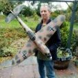
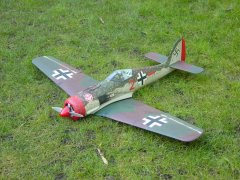
Flew the warbirds replica 190 this morning, using Ron's excellent dolly,it flew well no trim needed,might take a bit of nose weight out for next time.All in all pleased with it7 points
-
Hello Geoff Nice model! His designs are always good, the sports models fly perfectly and the "scale" designs are a good compromise between scale and flyability. I've seen some detailed-up and they look great. The same goes for Flair of course. Grahame Well summer has arrived, at least for today! That gave me something of a dilemma, should I go flying to get some thumb practice, or assemble the SE5a and take some “good” outdoor shots. I decided on the latter, which was the right decision as it turned out because the wind ended up quite strong; the streamers on the interplane struts were blown horizontal. To assemble the model actually took 20 minutes, not too bad, but longer than I thought it would be. I have only done it a few times and I’m sure I will get quicker with practice; I did make a couple of mistakes which meant I had to reverse a bit. The photos have turned out well; the only problem was the “giant” dandelions, which I’ve removed with the PhotoShop clone tool. I’m no expert when it comes to photo manipulation but so long as you don’t zoom in too close the overall effect is OK. I think the hangers in the background really add to the photos, hope you agree. I’m getting to quite like this photo manipulation! On this one I’ve also removed the grass overlapping the wheels, which gave the game away somewhat. A black and white “grainy” photo more like WW1. When I checked I found that I hadn’t in fact got a photo of the finished cockpit so I took a pilot’s eye view!3 points
-
Or use one of my new self powered and flight controller / GPS equipped ones that automatically returns to base! Having said that, if you're flying on your own take off at a slight angle so that the dolly runs off to the side leaving enough room to land, if you're with flying buddies get one of them to retrieve it for you!2 points
-
Built this Pushycat yonks ago. Only needs a prop and some courage to hand launch it lol. Cheers2 points
-
This afternoon was quite reasonable, not much wind and no rain so a bit more EDF practise so I got out my first foam build Hawker the Sea Hawk.I had not flown it for 2 years. Although the photo is nearly 3 years old it still looks exactly the same today. The inlet ducting is far from perfect. Any yaw any you can hear the fan note change and the direction of the inlet airflow is disturbed. With its generous area straight wings it does fly passably well although it needs nearly full power to climb. Like most 50s jets it has a low drag airframe so glides really well for and EDF. Managed 5 minutes 28 seconds which is rewarding. That leaves 2 more of my Hawker jets to fly. The P1081, the second swept wing Sea Hawk that crashed and the prototype Hunter. They are both painted all over pale sky blue that Hawker used on all their jet prototypes. It may be scale but they are just horrible to see at any distance!2 points
-
I had inlines on order from mid last year and in the end Jon offered me me single 155's so I went for them. As I understand the issue is of design vs manufacturing (all things are compromises) and some engines suffer with the issue and some don't. Its not so much a part that can be swapped, but more a fundamental design and manufacturing decision. The redesign would involve a number of significant component changes, but as I said not all engines are affected. I guess you need to run it to see which side of the fence yours sits, if there is an issue then involve the Laser warranty sooner rather than later. Perhaps that is why they were sold as development engines, so that people ran them and then issues would come up and be resolved, a bit like the petrol engines some sold and very few ever run and little feedback to Jon so very difficult to know if its an issue or not.2 points
-
Hi Steve and Guys, I am still working on the CAD files, and will then do some more testing. I just need more time!! Trust me, Xfire will live again. Cheers for now Pete2 points
-
Amazon offer the best Lipo service that I've experienced in many years. With Amazon Prime you get next day delivery, including Sundays, of the very good value Zeee Power lipos, with great quality at a competitive price. These have replaced my previous favourite HRB lipos from Amazon, which got so popular their availability of some sizes was impacted. The customer service is second to none. I check my new lipos the instant they arrive and any problem or inbalance is dealt with right away. Last order one of the packs had a badly unbalanced cell and the refund and reorder was sorted within minutes, with a replacement pair of lipos arriving next day, which meant I got three for the price of two. Highly recommended. Other retailers can be a bit more awkward if there is a problem, plus there is that mandatory courier charge and my Amazon Prime more than pays for itself every month, even without all the additional benefits.2 points
-
Thanks Keith, worth a try! While I wait for the fine lapping grease and some fresh cast iron for the piston thought I would do some boring bits. The needle itself has been made as my friend suggested, in the chuck and with a grind stone in the dremmel (and it at maximum rpm) shaped the needle point quite well. Turned a needle collar and soft soldered the needle and collar together with little fuss. All screws up and down with some nice resistance which I hope will resist the fine vibration of this turbine like engine... Next came the top of the cooling head and decided to add some more fins as the rest of the sleeve, more heart-stopping parting off tool work, what a din! Soaked the steel cylinder in citric acid solution, 20% crystals and had a good coat of bubbles on the cylinder after 10 mins. all rinsed and it looks much better, but still needs some swiss file work. Oddly, now ground to a halt, little else to do until the iron and grease turn up. Can this adventure (to me) actually be drawing to a close? Plan was to have it ready to run (really?) by my birthday, end of this month. Will i make it? Doubt it! 73T 911 Coup2 points
-
Test flown this afternoon, built from a Derek Woodward plan as an i.c model (not by me), bought from APOB and converted to 3s electric. Chilton DW1, i plan on building a larger one using foamboard and depron at some point.2 points
-
I have! In fact, I am still at the field, having a coffee. Lovely day with very gentle breeze... Longest flight on Alt, 1 minute 12 seconds. Well pleased.1 point
-
It is very forgiving on the CG position, as I said in my thread, mine is now at 100mm back from F2, a full 30mm back from plan indicated! PS Glad you like the dolly Andrew!1 point
-
Good one John M. Following the RM Plan numbering sequence I found It appeared in the June 1981 edition of Radio Modeller. Unfortunately I don't have that magazine in my collection but there is a copy on eBay.1 point
-
I had a look in an old plans handbook and I think that might be an RM239 by Brian Peckham. The plan is still available from Sarik Hobbies if you want to have a look yourself. Right wingspan and the tail looks the same?1 point
-
The website mediabiasfactcheck.com summarises The Daily Sceptic thus: "Overall, we rate the Daily Sceptic a far-right biased quackery level pseudoscience website that frequently publishes false and misleading information regarding covid-19 and science in general." Full article here.1 point
-
It's those that challenge those obvious truths that have the political or financial motives, or are unable to understand fairly basic science.1 point
-
Had two good flights yesterday with The Beaver. Nice flying plane. 24th of March 20241 point
-
That's the point, I'm not paying that inflated price, I'm getting those excellently priced Lipos from AliExpress at the much better cost that I posted.1 point
-
It's probably the same stuff that your 'banned' outlets supply anyway!1 point
-
I’ve used carbon rods with thread extenders expoxied on and they haven’t been an issue on any models. Including gassers.1 point
-
I have used a right angled bend on the end of the wire pushrod with a corresponding hole in the side of a carbon fibre tube. Insert the wire and juggle the end into the hole. Then insert a dowel plug of suitable diameter to fit inside the tube with a groove cut to suit the pushrod wire diameter and epoxy into place. It won't pull out. * Chris *1 point
-
To get battery in I did change a few things, I am using a 3s 3500mah lipo. so I used ply instead of balsa for the relevant formers to support the weight and the underside sheeting is1/6th ply, the holes in the formers shown on the plan were just to allow for the wiring so I enlarged those to suit the lipo which slips in nicely around the c of g position, the servos I have moved back behind the lipo for ease of access which will also allow me to slide the lipo back and forth to adjust the c of g position if required, I did intend to mention all this before but got carried away and pressed the send button! I had to make a few small 'adjustments' to ease it in, plenty of room to move it forward if I have to as the next bay will be empty apart from the esc.1 point
-
Nice engine......1 point
-
Despite all the little 'add-on' costs that arrive at check-out, an the challenge of actually finding what you want, it's still pretty good, and you will save money if you're patient...... I do feel guilty using them but assuage my guilt by buying online from the UK based shops as well.1 point
-
Flyer The method when using brown paper, is to paste it, wait 1 min for it to grow, then apply it wet, so when ironed on it shrinks like appling any film covering, this adding strength to the model. Using a cheap pva - it'll be watered down more, not good as bubbles the paper. Bye a quality brand 😉 and dilute about 5%, Richards just done a write up on this on another thread.1 point
-
Thanks guys- A bit of investigation of the hieroglyphics finally caught the blighter! I was worried that my translating back would be a one off, but, having clicked on another AliExpress notification in my emails, it's seems permanently back to good old English! (no Scots translation though!!)1 point
-
Possibly, but its an expensive way of doing compared with PVA glue (when you buy 5L of trade stuff). Oh and the other thing if its Tesco (other long rolls of brown paper are available) ..don't buy a couple extra rolls just in case...because you don't waste much in off cuts so it goes a very long way! PS the brown paper stock I now have will out live me!1 point
-
My glue of choice at the moment is Titebond Original, which I believe is an aliphatic glue. Are aliphatics any good with the brown paper covering method / heat reactivity, or will I need PVA? Cheers.1 point
-
You have to be extremely careful with AliExpress that what you are actually ordering is what you are looking at in the picture. Very often the main page for an item will contain lots of small pictures, with vastly different prices for completely different items. At first glance it might look like you are setting up to buy a model at £3.19, but what you have actually selected is a replacement wheel. As for how cheap things are, sometimes they will have a very low price, but heavily weight the shipping charge, which can be as much or even more than the cost of the item. Bear in mind you'll have to factor in the VAT if applicable and add that to the cost - the final cost shown is what you will pay. Pleasantly surprised to receive my latest order from them this morning 6 days after placing the order, when the predicted delivery date was 9th April.1 point
-
The company and its original Airlander was based in one of the airship sheds at Cardington (Bedfordshire) until a few years ago. That is about two miles from our club's flying field, but we never had any issues. It could often be see flying in the area. Following some issues, the use of the Cardington shed was no longer available and the Airlander was then moored outside. One night it broke loose from its mooring and was shredded by hearby hedges and laid in pieces on the ground. I have heard no more of it until now. It's interesting that the idea seems to have been resurrected. Most of the airfield at Cardington is now being covered by housing, though the sheds are used (for film work) and are listed so will stay. A couple of pictures. Brian.1 point
-
Not the nicest looking of the ARC range but all were/are good flyers. Will be awaking my Jupiter from winter slumber soon.1 point
-
Thank you for this valuable advice Dr. Trying to get in touch with Hemmingway today to get a bar of cast iron while I await the 1200 grade lapping grease to arrive. I have had a rod through the prop 'nut' as in the pics to turn the engine over repeatedly. Without the head on there is a light resistance as the piston is driven by hand up the bore, this could be a touch of binding due to the piston not being dead true to the various parts. This is with the cylinder tight to the case via the 4 nuts but no gasket between the case/cylinder. I think the piston is too slack in the cylinder, hence making a new one to match the honed bore. I made the piston really close to the un honed bore, my mistake. Same for the contra piston. Will try to make something to spread the C/P as an experiment and if it works will save me making one again!1 point
-
Thanks John. I missed that one even though I saw Hamilton go out. sorry for the delay answering.1 point
-
There is a problem with GPS if you have fast planes that also turn tightly as it seems that over a certain level of calculated G the GPS system assumes the latest position is an error and substitutes an interpolated position based on the last "good" track. Phil Green referred to this earlier. I did some experiments with GPS on my F5B planes back in 2016/17 and abandoned the idea as the results were useless. F5B fly up and down a 150m course at high speeds with very tight turns at each end of probably around 10G+. The GPS system was rejecting the latest positions during the turns and substituting assumed positions based on the previous track on the straighter bits. After a few more readings confirmed it really was now heading in the opposite direction it jumped to catch up - by which time I was beginning the next turn 🙃. The attached image shows the result. The yellow line in the middle represents the 150m course I was flying, and as you can see the GPS trace shows I appeared to be overshooting by about 300m in both directions. As a bonus the recorded max speeds were in excess of 300Kph 😀. The GPS sensors in use were the SM GPS Logger or a home built one based in this article https://www.rc-thoughts.com/jeti-gps-sensor/ GPS works fine on my slower gliders for GPS Triangle racing where I use the RC Electronics system. Dick1 point
-
Question for any seasoned metalworkers out there. I'm somewhat familiar with binding and soldering piano wire for UC and cabanes and suchlike, or soldering mild steel washers to piano wire, but, I've not soldered brass tube to piano wire. Intended use is for a DIY torque rod which needs to be, a) longer than the usual prefab 12g offerings and, b) double ended (!). I have some KS tube & wire which fits together perfectly. Is there anything special I need to know about prepping? My toolkit is a basic torch, leaded solder and flux.1 point
-
I regularly solder brass tube to piano wire to mount wheels. I over hang the wire slightly so I can drill a hole for a split pin and washer for scale(ish) wheel retention. It was the method suggested by Dudley Pattinson for the SE5a kit I built as my 3rd model back in 1996. Never lost a wheel yet and all I cleaned/tinned was the wire because of the difficulty getting inside the tube. Brass solders very easily. I use Fluxite to make it easier.1 point
-
Best to use an aggressive flux such as Baker’s Fluid as cleaning the inside of small diameter tubing effectively is rather difficult. Just ensure the workpiece is washed thoroughly afterwards otherwise it will corrode.1 point
-
If you want some real grip then really roughen the surfaces. You mention torque rods so perhaps grind notches in the wire or similar.1 point
-
The theoretical top speed for my SE5a using the 16x4 prop is 26mph, this gave me some concerns, however, looking at a ”typical circuit” eased those concerns somewhat. At 18% scale the speeds would be: Take off: not below 9mph Climb out: 10.8mph Level flight: 14.4mph Touchdown: 8.1mph The maximum speed is given as 123mph, it doesn’t say if this was obtainable on engine power alone but somehow I imagine this was the absolute maximum speed the airframe could withstand before the wings ripped themselves off or something equally terminal happened! At “scale” speed this equates to 22.14mph so my theoretical top speed of 26mph sounds reasonable. Of course the theoretical top speed doesn’t take into account the drag factor and models always seem to fly faster than “scale” speed but in practice it has worked out OK so I’m happy to stick with the large prop even if it does mean that the engine is somewhat “over-propped”.1 point
-
On field assembly is certainly the main drawback for biplanes. However, My DB Gypsy/Cirrus Moth (as seen in my icon) is quite quick and looks quite scale in flight though nothing as detailed as Greyhead's beutiful SE5a. Boddo devised a simple method of attaching the interplane struts which I've adapted for my Flair SE5a to replace the 8 nuts and bolts which were a bit of a pain. This was the maiden flight before I fitted dummy (elastic) flying and landing wires. The interplane struts are held to the top wing with 14 gauge bike spoke fed through split cotter eyes and held in place with a rubber band - quick and simple for a sport-scale builder like me 🙂 However, biplanes remain my favourites even though they get flown less frequently than my simpler airframes.1 point
-
The exit pipe once again uses a 10mm copper pipefitting and in this case also some 10mm brass tube; all silver soldered. The exhaust will exit via 2 of the holes in the engine under pan, not the scale exit points but at least I’ll have 2 exhaust trails following the model. The complete exhaust system. I ordered a new Laser 70 today so it shouldn’t be too long before I can start to test everything. If all is OK then I’ll trim the ends of the exit pipe to be inline with the under pan when attached to the model so in practice they will not be seen. If the system isn’t satisfactory then it’s back to the drawing board My new Laser 70 has arrived and of course it ran flawlessly after starting “first flick”, not that you’d expect anything less from a Laser. I should point out at this juncture that I have no commercial interest in Laser engines; it’s just that they are such good engines that I can’t stop “singing their praises”! Although the excuse for getting this new engine is the SE5a, in fact I’ll use one of my older, well run, engines. This one will free up one of my other Lasers by being mounted in the AcroWot and have a good few flights, first without the cowl to ensure really efficient cooling then after a couple of hours flying time with the cowl fitted. A fully enclosed installation such as the SE5a isn’t the place to bed-in a new engine. I have modified the crankcase breather on all my Lasers to make it easier if the engine is mounted close to the firewall. A short length of brass tube is soldered to the nipple; without it the fuel tubing extension would have to make a sharp 90º bend, which has a tendency either split of restrict the breather. I make it a “T” so it’s just as good if the engine is upright or inverted, the extension tube is fitted to the appropriate side and the other is blocked off. I ran the engine both with and without the SE5a exhaust extension and the only difference I could tell was that the exhaust note sounded a bit quieter with the extension fitted. One thing that I did find out was that I’ll have to incorporate some form of strap because when I opened the throttle above about half way it blew the extension off. Before I do any more testing I’ll run a few tanks of fuel through the engine to get it settled down and fit the strap. For the next tests I will get more “scientific” results on the effect of extending the exhaust by using a rev. counter, which I don’t own, but I know a man who does! Although I’ve not yet done any “scientific” tests, I should be getting a loan of a rev. counter next week, I have carried on with the installation of the exhaust. Having run the engine both with and without the exhaust extension I applied my usual method of decision making; if it looks / feels / sounds OK then it most probably is OK! I silver soldered mounting brackets to the exhaust and squashed the ends of the pipes somewhat to fit through the holes in the under pan. 2 hardwood blocks epoxied to the fuselage sides to screw into completed the installation. I trimmed the pipes so that with the under pan fitted the exhaust doesn’t protrude and isn’t visible when viewing the model normally.1 point
-
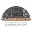
The SE5a was developed well after the time of dropping hand grenades or bombs by hand from the cockpit or shooting at the enemy with a pistol. The load it could carry was limited so 4 bombs of 20lbs each was the maximum, either as 2 sets of 2 bombs, one under each wing or a rack of 4 under the fuselage just aft of the undercarriage legs. The bomb release, operated by the pilot, is the out of focus black lever mounted low down on the cockpit side. Pulling it back released a bomb, pushing it forwards reset the ratchet system, pulling it back again released the next bomb and so on until all 4 bombs had been dropped. The bomb release mechanism on the SE5a is very complex, no surprise there then Although of course it is a proven design there is no way I could duplicate it in miniature so I’ve had to design from scratch. To release a bomb is simple, just a pin connected to a servo. But to release bombs sequentially is not so simple. I needed something that would be both reliable and practical at this scale; the full size Cooper bomb rack design would be neither! To control the release mechanism I only have either the retract channel or, if I invest in a new 8 channel receiver, a proportional channel. A proportional channel would be the easiest to work with but I don’t like the idea, if I turned the knob a bit too far a bomb might almost but not completely release then with vibration it could release itself at an unplanned time, which could be dangerous, or at the very least loose me a bomb. Having decided that the “bang / bang” retract channel it will be, I need some way of “stepping” the release mechanism. I got my thinking cap on and came up with an idea. I took my inspiration from a pendulum clock mechanism, these have been reliably sequencing one-second releases for over 350 years; the reliability comes from the fact that the “catching” plate is in position before the cog is released, but of course this produces a rotary movement whereas I required a linear movement. The “Eureka” moment was when I realised that staggered indexing pins could give the linear movement required. I made a mock-up to see if it would work in practice. The main release bar has 5 indexing pins spaced at 5mm intervals and will eventually have 4 bomb release pins each 5mm longer than the previous. The release cam has a slot cut out from the centre; before an indexing pin is released from one end plate by passing through the slot the other end plate is in a position to "catch" the next indexing pin. This is a series of photos showing the sequence as the servo moves the release cam arm backwards and forwards from one extreme to the other; the release bar steps by 5mm with each operation. At the moment I’m using an elastic band, the spring tension will need to be worked out when it is actually releasing bombs, I hope! Here’s a schematic showing one full cycle of the servo, 2 bombs released. Don’t ask me why I did it "stepping" right to left, must have been feeling a bit Chinese!1 point
-
Disappointing! What's the 'control unit'? We (well a club mate) gave a new member his first successful flights today - he'd only come along to watch having damaged his own model 'having a go'...... quickly realised there's more to it than meets the eye. He had 3 flights buddy-boxed on an electric Junior 60 and left with renewed mojo.1 point
-
With all the silver soldering complete (the large brackets are for fixing the undercarriage to the formers and will be bent to accurately fit when the formers have been made) it’s time to add the wood cladding. The legs on some SE5a’s were wrapped with linen so hard balsa could be used for the cladding but the particular aircraft I’m modelling didn’t have wrapped legs, they were left as natural wood, so spruce is the material of choice. As is sadly often the case these days my local model shop could supply me with an ARTF cloned SE5a but a sheet of 1/8 " spruce is another matter! The next best option was a length of “strip wood pine” from B&Q. All the blanks are fret sawed out, the fronts routed to take the piano wire then clamped and glued using slow epoxy before the rears are routed so ensuring a good join. I've got a couple of Black & Decker routers but the best way I’ve found to rout the blanks is to use an appropriate sized “ball ended“ router bit fitted to an electric drill in a vertical drill stand, adjust the height to cut half depth of the piano wire. Hold the blank in place and draw round the piano wire then rout down the middle of the lines. The bit doesn’t have to be exact size, once the router has done it’s job a piece of the correct gauge piano wire dragged down the groove will soon make for a good fit. What better on a rainy Sunday afternoon than spending a couple of hours in the modelling room happily “Dremelling” away at the SE5a’s undercarriage? The first coat of stain has shown up a few areas that require extra work so it’ll be out with the sand paper before the next coat. Then light sanding between coats to build up the “depth” of colour to represent the original hardwood.1 point