
Leaderboard


Popular Content
Showing content with the highest reputation on 27/03/24 in all areas
-
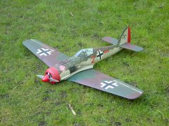
The build of my FW190 progressed well thanks to all who have shared their builds and learnings, especially to Ron for his videos.. Here is a sneak preview. It still requires weathering, panel lines, decals etc.8 points
-
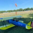
Just completed this and ready for maiden at the weekend as weather looks more promising here in the north east. It is Miss Lizzy, a Peter Miller plan from RCME September 2005. I am surprised how long I have had this squirrelled away, I always liked the look of it as well as the earlier smaller Tequila Sunrise. Since stashing the plan away I have swapped to electric only so I have converted this by making the space between F1 and F3 into a battery bay which has plenty of room for a 3S 5000mAh battery and cut a hatch into the top of the sheeting. Other changes are swapping the u/c to a small carbon fibre unit, 3D printing the cowl and moving the tailplane servos to the rear to offset the battery weight. The pilot and windscreen are also 3D printed. It all comes out to 4lbs 1oz including the battery and with 525W of power it should have good flight performance. ps, I have just gone back and checked Peter's build article (RCME Miss Lizzy build article) for the weight and that states 4lb 1oz, exactly the same as I have achieved with my electric conversion. Just curious if the quoted weight is with or without fuel, mine is in flying condition including the battery weight (13oz).5 points
-
I opted for this livery with yellow rudder and cowling.5 points
-
Yep, Laser ran through his veins, shame his bosses didn’t give him the support he deserved, absolutely disgraceful.4 points
-
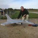
Still waiting for suitable weather but a picture of the X-3 with its long nose. This nose is not flight worthy. It is only for show as apart from any safety considerations the retaining magnets are not strong enough to withstand the likely aerodynamic forces from any pitch or yaw. If and when the X-3 does prove to fly well enough with the bluff nose I could in the privacy on my field tape the long one on just prove it will fly but landing with it undamaged is likely to be a different story.3 points
-
I think you have the lead in a socket marked VCC? This is not the throttle channel. Funnily enough, someone else new to electric power made this mistake very recently. Unlike an IC setup, the ESC needs to power the receiver through the channel that supplies the throttle channel position data. I believe this is channel 3 on this radio.2 points
-
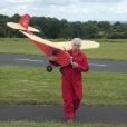
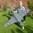
Both Bertie and Boris Baron are ready for La Coupe. There are a few cosmetic jobs to do but they are in serviceable condition I'm just waiting for the wind and rain to stop before flying them. Technical details: Bertie has a wingspan about 2.5 inches or 6cms bigger than standard, (my fault I changed the internal structure of the wing!) the airframe weight is 2.1kgs and the model is powered by a Magnum 52. Boris has the standard wing, weighs 2.2kgs and is powered by a Thunder Tiger 54. I'm told that my models are rather heavy. The weight of the four-stroke doesn't help of course but I used basswood for the fuselage longerons and though they have added weight, both models have crashed without the fuselage being damaged. My dog is such a diva that she has to photo-bomb at every opportunity!2 points
-
I installed the battery tray and the ballast box that I got from Ron after a little tweaking. My 4S 3300MAH battery fits perfectly. They really fitted well and very functional - Thanks Ron.2 points
-
Totally agree Ron, Jon w@s an exceptional ambassador to the brand.2 points
-
Or use one of my new self powered and flight controller / GPS equipped ones that automatically returns to base! Having said that, if you're flying on your own take off at a slight angle so that the dolly runs off to the side leaving enough room to land, if you're with flying buddies get one of them to retrieve it for you!2 points
-
I totally agree and I don't think anyone on this forum / thread is expecting you to! Whilst you instigated this thread and are its author, it has become the place where we are having a conversation about the state of play. By all means get the mods to close this thread and we will start a new one to continue this dialogue which won't drag you in!2 points
-
Hi Steve and Guys, I am still working on the CAD files, and will then do some more testing. I just need more time!! Trust me, Xfire will live again. Cheers for now Pete2 points
-
GReat to see Miss Lizzy. You will love her I am sure. Yes the weight is without fuel. ENJOY!!!!1 point
-
Probably safe enough if flying on your own.....1 point
-
Welcome back. It's not only models that fly - time does too!1 point
-
Hello Chaps, it's been over a year and I'm still in the same place regarding flying as I was then. 🤣🤣 I'm gonna dust off the thermos, make some sandwiches, catch up and then see how the land lies. Hope you are all well BTW. D.D.1 point
-
The last cast iron rod/bar I bought i found on Ebay, Mehanite grade. Also good for making new piston for old diesel engines. Previous to that I have used some old cast iron window sash weights. Failing that have a word with a GC piston rings Gavin might supply some. I forgot to say. Try to find the smallest dia bar as its often difficult to find anything smaller than 30mm and thats a of waistage and time spent getting down to size.1 point
-
Fantastic, thank you, all works now, sorry for bothering you with such a simple problem1 point
-
Modern parlance " its just business, nothing personnel". As a modelling community we were lucky the brand didnt ceace production when Niel retired some years ago. I hope you all get the modified parts for you inlines and get thdm in the air. Jon's position is just another example of collateral damage in the closure of the factory who it appears only mades Lasers as a side line. RIP LASER ENGINES1 point
-
If replacing the aileron servo, then it would be worth doing both or you might find mixing different mfg's you end up with different control surface deflections.1 point
-
Here is a mock up of where we are so far, control runs in, fuselage and tail ready for covering probably tomorrow. I want to get on with the wing construction as much as possible before the Easter weekend as the family will be home, guests arriving, which means that I will not be allowed in the garage for the duration! So, the centre section is built first, in one piece then cut in half once skinned. in the article Roy Salter mentions that the wooden dowels inserted as a sort of jig to keep it all lined up are sacrificial and cut in half then disposed of, I dont think that is nessessary so I will save them. First of course I have drawn some templates on some thin ply, the centre section is a constant chord, the smaller rib is the outer one on the wing tips, the intermediate ribs are not shown on the drawing so I will use the sandwich method to produce two (handed) sets. The centre ribs which take the wooden dowels are 1/8th ply, easy to do on the band saw, but I don't know how I managed that on my original model I must have used a fret saw, I really cannot remember! I managed to find enough scrap balsa to make all the balsa ribs, these are the centre section, the rest are 1/8th ply 8off The ply ribs are done, drilling the 12.5mm hole for the beech dowel was a bit tricky and even then the dowel was a very tight fit, so I wrapped some sandaper around the base of a drill and relieved the holes until it was a nice slip fit, I also sanded the dowel with very fine sandaper and then gave it a couple of coats of furniture wax as a form of lubrication, seems to have done the trick. The rest was easy, first laid down the bottom sheeting and cap strips The all the ribs using the dowels as suggested in the Roy Salter article to jig it all together, and also I have fitted the dihedral braces that will slip into the outer panels I have left a small gap between the centre ribs, enough to get a razor saw between them to cut the wing skins once the glue has dried and I have lifted it off the bench. Top skins and cap strips on, I have marked to centre line to guide the razor saw, hold my breath and cut it in half once all the glue has dried overnight1 point
-
IL200 posts moved to dedicated topic.1 point
-
I wouldn’t attempt it without self levelling. However, I only need to look down for less than a second - no worse than checking something on the transmitter screen. Nevertheless, it’s reassuring to know the plane is not going to do anything unexpected.1 point
-
Talking about IRL Ron, where R=Real, not R=Ron's 😉 Avid subscriber to Gray-O-Vision. 🙂1 point
-
Not a very good photo with the work table background, but together with the completed one it shows the motor mount. I have doubled up the firewall as suggested. Later I chopped off the motor shaft too so that nothing is sticking into the battery bay. I screwed the cowling as per Ron's suggestion so that it can be taken off. I added the cockpit details upfront. I have opted for installation of permanent servo cables for the ailerons enabling connection in the servo boxes. This enabled me to join the wings with no cabling effort. I used snakes with carbon rod and clevices Cyano glued, the connector is slightly crimped and shrink tubed at both ends. I also added snake outlet covers.1 point
-
Our strip has an electric fence to keep the sheep away, flying on my own I take off just before the fence , the dolly generally rolls over the fence (which is on the ground) leaving the strip clear for landing.1 point
-
So following what Jon said in the 'announcement' thread: The inline engines need one component replaced. It has been designed, manufactured, but not finished. Once available those with engines will be contacted using the list i kept of who had them, and i will find some time to sort it out. It will be done in my own time when i can, fitted in around a new job, new nephew, house move, car needing work etc. The upgrade will not be charged and you are free to take it, or not. Just note that there is likely to be only one chance to take it so if you decline then have an issue in a few years the opportunity will have been missed. It's good to know that the parts have at least been made but somewhat unfair on having to rely on an ex employee to do the work. From a personal point of view I think that I would like to fit the part myself (Jon did suggest that to me a while back) at least that way it may get done a bit quicker.1 point
-
I never was. I can appreciate your concerns, and i share them, but i was just an employee, and i have left the company. The harsh truth is that its not my problem any more and i am within my rights to not give two hoots about it. However, i feel it is rather bad form to just abandon those who tried to support what i was doing with the inline's and that is why i have agreed to do the work once the parts are done as i do not want to leave people stuck if i can avoid it. The reason why i am asking to call a halt to the conversation here is that in the past it would have been an avenue to communicate with the company through me. That link is now broken as it is no longer my job to chase parts and have long draw out customer service type conversations on forums, yet here i am at 9pm on a Tuesday evening. In any case, posting here will not yield any result beyond making me feel bad and dragging me back into a job i no longer have.1 point
-
The upper fuselage sheeting was again straight forward, I added a 1/4" longeron to support the top frames, which also gave the sheeting something to adhere to. The sheeting was achieved with 2 pieces cut from one sheet 4"x 48". The wing centre section ribs (Sarik laser cut ones) were 3/32" short with reference to the drawing, it would have been easy enough to produce replacements from the plan, but I used this to my advantage as I felt the wing attachment frame was a bit on the thin side (for my flying style !!) So I made a doubler on the aft face of the frame out of 3/32" ply. - problem solved. The aft wing attachment has been changed to 2 commercially available bolt retainers. . With the elevators and rudder, I made lightning holes to keep the tail end weight down.1 point
-
The website mediabiasfactcheck.com summarises The Daily Sceptic thus: "Overall, we rate the Daily Sceptic a far-right biased quackery level pseudoscience website that frequently publishes false and misleading information regarding covid-19 and science in general." Full article here.1 point
-
Thanks Keith, worth a try! While I wait for the fine lapping grease and some fresh cast iron for the piston thought I would do some boring bits. The needle itself has been made as my friend suggested, in the chuck and with a grind stone in the dremmel (and it at maximum rpm) shaped the needle point quite well. Turned a needle collar and soft soldered the needle and collar together with little fuss. All screws up and down with some nice resistance which I hope will resist the fine vibration of this turbine like engine... Next came the top of the cooling head and decided to add some more fins as the rest of the sleeve, more heart-stopping parting off tool work, what a din! Soaked the steel cylinder in citric acid solution, 20% crystals and had a good coat of bubbles on the cylinder after 10 mins. all rinsed and it looks much better, but still needs some swiss file work. Oddly, now ground to a halt, little else to do until the iron and grease turn up. Can this adventure (to me) actually be drawing to a close? Plan was to have it ready to run (really?) by my birthday, end of this month. Will i make it? Doubt it! 73T 911 Coup1 point
-
I’m not sure what’s given the impression that I’ve recommended adapting anything other than an unobtainable bearing. I thought I’d clarified that in my reply to JD8!1 point
-
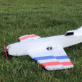
I've finally managed to finish off my Impala, the weather hasn't been very conducive to spraying so there has been the need for much use of the fan heater and hot air gun to help things along, my impatience doesn't help of course! I chose to replicate the colours of a recently restored Italian Air Force MB-326K Impala - registration I-MBCK. I had never attempted spraying camouflage with faded edges before so this was a bit of a new adventure for me. Fortunately, Harry Twist pointed me towards using soft edge masking foam which helped no end and although the masking process took quite a while I'm very pleased with the results. I once again used the Lifecolor Mimetic range of paints from Airbrushes.com. The rest of the detailing is a mixture of vinyl and waterslides and in some places waterslide on top of vinyl. The whole model then had a couple of coats of clear satin sealer to finish off. It turns out that paint and vinyl are heavy, adding another 140g to the finished weight so I probably now have the heaviest Correx Impala ever built at 1790g! That aside, with all the added 3d printed parts and detail I reckon from 6 feet away anyone would now be hard pushed to recognise its humble Correx origins. I'm now really looking forward to getting her maidened... when there's a stiff breeze blowing!1 point
-
Slow progress over the last few weeks. I have completed the wing root fairings and filled and sanded them to shape. Also, I have attached the wing servos on their mounting plates with hardwood blocks and small wood screws. The servo wiring has been run in the slot cut in the lower wing surface. I have filled in the slot with some balsa strip as I think that is structurally more sound than leaving it open. The downside is that I would need to cut into it again if I ever have to replace the wiring. Servo replacement is possible as I have made a plug joint in the servo bay cavity.1 point
-
I sanded the wing LE and tip to shape. Its probably the job I dislike the most but the result is always satisfying in the end! The wing tips are always the most difficult but it is a case of taking ones time and removing small amounts with checks all the time on the shape. I use a razor plane initially and then a Permagrit block followed by fine grade sandpaper.1 point
-
Some other little job. As others have done, I added some scrap balsa support to the cockpit sides where they splay out to join F2. Like wise, I also added a balsa top deck over the aft of the cockpit area to better support the cockpit side panels. I think this was faired in on the original aircraft. I will add a pilot and instrument panel later before finishing the model.1 point
-
Once again I have been presented with a kit of pre-ruined parts to make something resembling an aeroplane, one day I will build something from new !1 point
-
Almost there ,just a few to add like fake rigging and a quick dust of satin proofer and the inevitable wait for the weather to co-operate 😕1 point
-
That's the major wing repairs sorted out, just the covering and attaching the ailerons but before I do that there's the issue of the discoloration of the wood to deal with. The natural finish polytex will expose the difference in colour quite starkly, looking around the workshop I found this In the previous picture of the wing tip repair I have applied a coat of the paint and sanded it lightly and I think it gives the appearance of being from one piece of fresh wood? Well it does to my eyes lol ! this is perhaps a better illustration Now back too fitting out the fuselage U/C on,simples! Servos fitted in the same position as it was received in,however with the engine it was nose heavy? The joggle, cheap and effective. Works this end as well So far it's cost £20 for the airframe ,a small amount of wood, paint/fuel proofer and covering that I had to hand1 point
-
Just to bring you up to date on a couple of modifications to the SE5a. I had bent the axle to give a few degrees of toe-in. It did improve the tracking initially but because of an unforeseen flaw in the design I’ve now straightened the axle again. The axle passes through holes in the undercarriage legs and is held by bungee cords. Having bent the axle it was slightly “V” shaped and was positioned in contact with the base of the axle fairing with the apex of the “V” pointing to the rear to give toe-in. When I checked after a couple of flights the axle had rotated, the “V” was now pointing forwards, giving toe-out, exactly what I didn’t want! Presumably the friction in the wheel bearings produced enough torque to overcome the friction of the bungee cords, the ground handling wasn’t too bad before, especially for a model of this type, so I decided to abandon the idea. I moulded the noses of the bombs from rubber both for safety and to make them less prone to damage; however, the rubber I used has proven to be very susceptible to the effects of fuel / exhaust emissions, the detailing has virtually melted away and they are very sticky. I have replaced them with some dome shaped rubber feet from Maplin Electronics, they are made from much more robust rubber so I hope they will not suffer the same fate. As you can see from the photo the new noses are not the correct shape, are slightly too small in diameter and have no detailing but you have to be pragmatic about these things. I think they are quite acceptable especially with the arming vanes in place and when seen from a distance slung under the model.1 point
-
Hello John Thank you for the compliments, much appreciated and you're correct the smaller the scale the harder it is to detail convincingly but I 've never built "big" always as small as I can to fit the Laser in. Of course a non standard scale means few commercially available accessories which only adds to the fun! Biplanes have loads of wing area for lift but also loads of drag to overcome so you need a more powerful engine to fly at any given speed, more of that in this post. Grahame Just got some more information; the maximum speed with the 200h.p. Wolsey Viper was 138 mph so obviously they didn’t fall apart at 123 mph! At 18% that still works out OK for my model at just under 25 mph. not that I really want to fly at maximum speed, I prefer low slow passes! Once again no photos, can't fly and use camera at the same time! On the last trip to the field it was a flat calm, very unusual for our Redmarshall site. As expected the take off run was considerably longer than on previous occasions, although the grass is kept short, at scale it is still the equivalent of taking off in a field of mowing grass so there is plenty of rolling resistance. If the model is taking off into a 5 mph wind then the airspeed is 5 mph faster than the ground speed; it even has an air speed of 5 mph when standing still! What did surprise me was the rate of climb, or lack of it, once the model left the ground. In fact by the time it had gained sufficient height to make a turn I was quite concerned that it was so far away that orientation would soon become a problem. This is where I made an “error of judgement”; I turned the model to the right. The model lost some height executing the turn and was now only just visible above the hedge line, then I realised in the direction the model was now travelling the ground was rising at a gradient about the same as the models rate of climb so there was insufficient height to make another turn, so I closed the throttle and set the model down in the middle of the barley field. When I got the model back I tried adjusting the needle valve just in case the engine wasn’t quite “on song” but it had no effect. I tried again; this time I was better prepared and had a successful flight but I’m going to try a smaller diameter prop to increase the engine revs, hence the maximum air speed, because although the model flies OK it is obviously marginal. I’ve ordered an APC 15x4 but I’m going away in the caravan for a week so it’ll be after that before I can test it; watch this space! My 123 mph maximum speed for an SE5a is way too slow. Information I’ve received suggests that they could in fact reach 225 mph safely in a dive, I say safely because presumably the pilots survived to tell the tale! I have realised where I made the error; I was quoting from an article about the Shuttleworth restored SE5a and the 123 mph must be the maximum speed that this is allowed to fly at these days, obviously they’re going to be very, very careful with such a valuable machine. I assume that the take off and landing speeds are still comparable to WW1 days.1 point
-
Just the radio install now(and line up the rudder stripes properly ?)........1 point
-
ell,think it's time to resurrect one of my old threads ! The reason for the build stalling was that old bugbear of mine the dreaded fuel proofing ?now it just so happens that I recently (as in last year!) needed to respray a motorcycle l built,so l got a spray gun and paint and set to it.Which turned out o.k and now ment l had 1.the equipment for spraying 2.the 2k clear fuel proofer I also had to strip the godawful Solafilm polyester off the tailplane and replaced it with Hobbyking film rebuilt webra 61F on custom backplate mounting ,and now to deal with the other thing that l had been avoiding, the cowling! Again this was as a result of making a couple of custom side panels for the bike that ment l had the materials and (a bit) of experience to make it foam blank all g/f up and waiting to cure ?1 point
-
Nice rendition of Udet’s D7 although there is some doubt as to the colours used, it’s a shame that after going to all that effort to apply a scale colour scheme ( been there, done that , doh ! ) that there is not one dimension that’s close to being right ! Never mind, it’s only aerophile’s like me that would spot that ! I was lucky to find six NIB FP-S 111 ‘s you can tell that they are old as they have MADE IN JAPAN printed on them ,linear servos are ideal for things like this and for the throttle. This may be of " interest " if you like Fokker's that is ! Edited By jeff2wings on 25/09/2013 22:53:361 point


(2020_03_2622_00_27UTC).thumb.gif.375a6ebc5cd681eb724c62879a10ef8d.gif)