Leaderboard


Popular Content
Showing content with the highest reputation on 22/02/21 in all areas
-
Phew! Thank goodness for that! I'm nowhere near having my current build finished in time for the 8th... but the 29th is looking feasible! ?2 points
-
Well as I am now happy with the chalking I removed it with a damp cloth and replaced it with Humbrol dust wash using an airbrush. Last will be to airbrush some smoke wash for the exhaust and gun stains and add some chip marks/wear on the walk ways.2 points
-
... for those who missed it, today's Alfa Romeo presentation at the Orlen HQ in Warshaw... Enjoy... Cheers Chris2 points
-
So I'd thought I'd try and document the build for this model. Please be aware this is only the third model I've built so please bear with me. So I thought I'd start easily, with the rudder & elevator these are all on one laser cut sheet for ease Next up is the elevator parts laid out and pinned down, all parts are numbered and shown on the plan. Elevator all glued and pinned Next up is the rudder which is done in the same manner1 point
-
I'm expecting my new labels to outlive any of my current models. I'm sure that anyone who has seen me fly will agree.1 point
-
Thanks once again Mike. This makes perfect sense and gives me some reassurance that MPMs can offer comparable range to the original manufacturer's equipment. This is one of the things that I love about forums like this and the internet in general. You are never far away from someone with the knowledge you are lacking and is willing to share it, or point you in the right direction. People like you are what make it possible. ?1 point
-
Welcome to the forum hambush. You say you want to scale down a slope soarer design by 50% but essentially achieve the 'same performance' by perhaps using a different wing loading or aerofoil section. So what exactly do you mean by 'performance'? Speed range? Ability to penetrate? Soaring qualities? Stability? Aerobatic agility? I suspect that you may emulate one or two facets of its larger stablemate's handling but changing one parameter will effect another to its detriment. However the new smaller model that you have created may still be a delight to fly, just a little bit different to its larger brethren. An interesting project and the best of luck. ?1 point
-
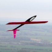
Great work as usual Danny, My son built one of those with a big Plettenburg brushed motor. It was sold unflown . The fellow who bought it said he had a job getting it down, it just wanted to float on and on.1 point
-
You need to research cubic wing loading, basically as the model gets larger then the wing loading can be higher for similar flight conditions. So if you reduce the size then you need to reduce the wing loading to maintain the flight conditions. There's an online calculator here1 point
-
Very Nice Mate. D.D.1 point
-
Cont'd Not strictly in order, the last two shots should have been with the previous post, but you get the idea. Cheers Danny1 point
-
Took a look at adding flaps. This is a lot of work for simple split flaps, but what the heck. First I made the flap skin from G10 (fibreglass board) this is the thicker of the material Mick Reeves sells. Then I fashioned some ribs from 32nd ply, mounting them on a 4mm carbon tube. Once the wing trailing edge was removed I could see three circuit board hinges would suffice. The flap was a little flexible so I added ply diagonals, it is much more rigid now.1 point
-
Nobody commented on my gadget for inserting threaded ends into snakes - so either you all understood or perhaps nobody did! So here is a slightly better picture of the gadget made from an opened out metal clevis and a bolt ( actually a spare threaded end with a blob of solder to form a head) The bolt is simply screwed until it meets the threaded end and then it 'locknuts' it enabling the threaded end to be driven into the snake, then when bolt is unwound the clevis bit simply comes off without unscrewing from the snake.1 point
-
I think we'll do very well to wait for guidance from the BMFA, but on the face of it, if organised team games like football which will involve at least a couple of dozen people turning up at a field to to kick a ball about will be OK from the 29th, then I expect a sensible conclusion would be to assume that a flying club would be able to operate pretty much as before but with the on-going precautions. Personally, I'm happy to wait a bit longer until the waterlogging subsides! At least there's light at the end of the tunnel for the hobby and the nicer flying conditions in the late Spring and Summer.1 point
-
Further to Mike's excellent post above, here are some good resources on the fine tuning process on an MPM based radio... Multiprotocol Module Frequency Tuning - YouTube RadioMaster TX16S The Need To Fine Frequency Tune FrSky Receivers - YouTube Oscar Liang written guide to frequency fine tuning1 point
-
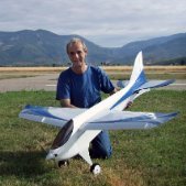
With the structure substantially complete and the wing bolts in place it is possible to not only work out if a 'workable' CofG but the airframe can undergo my standard 'strength test'. At the normal flying weight can it be supported by just its wing tips? Not exactly scientific but its puts a root bending load roughly equivalent to pulling 4g. My guess is it could easily support quite a bit more but at this stage I didn't want to break anything. ? The next task was to see where the battery had to be placed with two 3.7 elevator servos placed on the tail plane to give a CofG at 25% of the mean chord. The answer is a long way forward! ? The ESC and Rx also well forward will ease things a bit. This will also have the side effect of making the weight of all the wiring almost CofG neutral. The final problem yet to be solved is how to launch it? As its wing loading is so low I do not expect it will require much of a 'shove' but the fuselage is way too big to grip so it may require 'bowling ball' type finger holes in the underside as I did with the bigger & heavier AN124.1 point
-
Little bit more done today around blood tests and visit to doctor. I have also been working on ideas for the Bobcat project, so got less building done.1 point
-
1 point
-
To give some background to all this. Both a Tx module and a Rx rely on a crystal oscillator to provide an accurate frequency reference. The exact frequency then used to transmit and receive is derived from this. It appears that FrSky modules and receivers use a crystal that is very accurate so any module works with any receiver. It also appears that the crystal in MultiProtcol modules, for the CC2500 RF chip, is less accurate, hence the requirement for fine tuning of the frequency. I don't know the accuracy of the crystal in the R168. One of my MultiProtocol modules needs a fine tune value of -40 and another needs +40. If I use the one that needs -40 with a setting of +40, then it won't bind or operate servos. If someone has both FrSky receivers and R168 receivers, and a MultiProtocol module, it would be useful to test the MPM with both receivers and see if you need the same fine tune value for all receivers. If you need a significantly different value for the R168, then I would suspect the R168 crystal is less accurate, and would question if it was good enough to use with a FrSky Tx module, more testing would be indicated. Mike1 point
-
I guess, if you limit it to only two members on site at any time. Really I would have thought 29th would be more appropriate.1 point
-
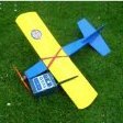
Hi everyone I came across this old thread when practicing in the new forum so I decided to post my first post in the new forum here. The Somethin‘ Extra is now fully built and equipped with a 52 engine and a 11x6 prop. Hopefully I will have the courage to maiden it this summer. B.1 point
-
Of course, I could always go for the fixed u/c option. I've found this photo! Would need small props though as there is little ground clearance.1 point
-
Interesting. According to the website shown at the bottom, there is a long list of protocols that require tuning when using a Multi Protocol Module. I use a Jumper 4in1, so I assume that it applies to them. I wasn't aware of this but I'll be looking into it. Regarding where to find the option, that screen looks like the Model Setup screen used for binding in OpenTX. https://www.multi-module.org/using-the-module/frequency-tuning Edit. No I don't use the Jumper 4in1 for native FRSky products and neither does your QX7. We use the internal module. This procedure is for using MPMs including Radiomaster transmitters, with the listed types of receiver.1 point
-
Well, it's been nearly a year since anything has been posted. Struggled to find time for various reasons but will endeavour to get this one finished. First set of pictures show cardboard templates for cooling baffles Finished baffles should provide adequate cooling Next job is to start with panel lines etc1 point
-
I think we are all hoping Mike is designing a new model with intentions of publishing the design - we really need up to date designs! In that case I suggest a published design should allow for the fact that some of us fly from rough grass strips so a tough u/c and ply doubler may be important. The doubler should be shown and could always be left off by those who want. A torque rod u/c works well but not everyone likes bending piano wire, so again the option of a carbon u/c should be shown. Fuselage mounted u/c is better in my opinion and it's so much easier to store and transport a model without u/c on the wings. A while ago in the Ballerina mass build thread one person decided a built up tailplane would be lighter and I doubted that and said there was not much advantage over solid balsa well chosen. So it ended up a challenge - i built a solid one, the other man built up and we both weighed them. I lost but the difference was so slight it was acknowledged that it was not worth while building up from strip. So I feel a solid tail is more attractive to builders. Less vulnerable to damage in transport too. Nowadays there are lots of experienced pilots who have little experience of building. New designs should allow for that. My pet hate is plans that are CAD drawn with formers etc that are so fiddly they can only really be lasercut and are not at all easy by hand cutting methods. Several designers seem to relish the idea of complex interlocking parts and use them everywhere! The good old straight former designs appeal to me much more. Am I alone in this?1 point
-
I was about to add that I fitted my OS 52 Surpass to the nylon engine mounts of my Sig 4 Star yesterday and that 4mm bolts were a good fit... I used nuts, bolts & washers, though I have used self tappers into nylon mounts in the past without any problems. I have also drilled and tapped nylon mounts and just used standard machine screws, also without problem, though there is a limit to how many times you can remove and replace the engine using this method.1 point
-
I've a few matters to consider right off the bat. I had a look at my balsa stocks and found that while I'd only got four strips of 1/4" square, I have nineteen in a size is very slightly larger. Using my much abused RCM&E guage I each able to confirm that the larger section wood was too big to fit into the 1/4" slot and too small for the 3/8" one. My cheap and cheerful Draper guage measured the larger wood at 7.5mm or about 0.29". Pictures below may clarify or confuse! Where I'd bought this wood from I cannot recall but it is certainly neither 1/4" square nor 3/8" square. I see that SLEC advertise their 1/4" square as 6.5 mm square and I'm informed that they have been machining balsa to metric dimensions for some time. French suppliers specify 6mm x 6mm. I retired to central France in 2015 incidentally. I am left in a bit of a quandry. Should I use the thicker wood for the Big Guff's basic fuselage construction or should I order some 6mm square from a French supplier? The larger section balsa seems to be of a lighter weight than that which I would normally use for fuselage longerons but the fuselage will be completely clad in 1/32" balsa anyway. If I order some 6mm square what am I going to use the 7.5 mm stuff for?1 point
-
A good source of nuts bolts screws etc is Modelfixings Great web site and better than average price for delivery quick post Usually day after1 point
-
There's many ways to skin the cat ?1 point
-
Well the plan is in very good condition, so I'll get it scanned in the next week or two and then forward it to Outerzone for you.1 point
-
Thanks for the comments guys ! The elliptical ones i do with wooden templates Nigel , or flexible plastic drawing tools. these are the hardest to do !! I'm afraid i'm still drawing panel lines ...The ''good'' news is that i'm halfway this process ... Some images : Getting bored with these lines i tried another detail yet to do :some 60 DZUS screws. These were also stickers under paint on the PSS fuse but i'm testing another methode : Real screws ! About 5 minutes per screw , that schouldn't take too long ! Thanks for watching ! x1 point
-
All the tools in the workshop would regularly go out for a drink on completion of a job. But never invited the anvil co he always got hammered... The Taxi hasnt arrived1 point
-
8AE9D6F6-5EA4-4A2C-A451-17464507CC3B.MP41 point
-
Thank you for the comments. This has a few firsts for me. 1st proper powered purpose designed aerobatic. 1st plane with retracts 1st homemade vacform 1st go at glassing... Now I have been a model maker for a lot of years mostly gliders/yachts and I'm thinking I might know Martin Kinder if he is the same chap I have raced RM's and 1 metre yachts against back in early 1990's at Fleetwood/Birkenhead etc in the Northern District. In an earlier post he mentioned Housemartin and Bantock for equipment and that got me thinking. Anyway back to it. Sanding,sanding and more sanding. I've opened up the cowl and added the 1/64 ply hard edge ready for microballoon and epoxy fillet. As you can see I've tapered the ply edge ready to take the fillet which I'll add after glassing the cowl. I also sanded and smoothed the exit for the elevator and rudder controls upper one is elevator lower one for closed loop on rudder The elevator is two snakes one each side joined to a common servo. I then spent this evening cutting templates for the cutting of the glass, and applied to the battery hatch, elevator(s) and Rudder. I used cheep hairspray to hold the fine strands while cutting it worked suprisingly well. I useed an old plastic card to scrape the epoxy into the glass and remove the excess resin, this was suprisingly easy having earlier done the cockpit floor on Saturday evening. However I've not had the best of luck in getting the glass to drape over the edge. I'm not too worried about that as I can always edge separately. In the las picture you'll notice I have used the remaining epoxy to re-coat the plug for the canopy i've learned another first... It doesnt like being applied over Ronseal Diamond Hard varnish! In friday's post there is a photo of the Vacformed canopy but it shows a slightly mottled effect this is because the Roneal sofened under the temperature of the hot plastic - so I'm going to pull another with the plug hardened with epoxyand wet/dried. Hoping to have done most of the glassing by next weekend but we'll see. N1 point
-
As pointed out in earlier posts, 3.5mm fixings are easily available so why not just use them?1 point
-
One drawback of drilling engine bearers is it reduces the resale price of the engine if you ever want to sell it . I disagree ,JMO about " sufficient meat in the beam mount flanges" and have seen many drilled mounting lugs snapped off. A drilled engine is only worth spares or repair mo ey even if it's a good runner . Again I stress JMO and don't want to start a bun fight but many of the IC brigade will probably agree that drilling engine cases/ mounts is not recommended.1 point
-
And here is the video of it second run. I did the first one this morning with the cowl on but I had a problem with my remote glow so it only ran on 1 pot, mind you it still pulled 5K on just 1! After the rain stopped I took it out again with the cowl removed so that I could put 2 separate drivers on the plugs. Things to note, I need to adjust the slow running as it's still not quite right, but top end is giving me 8.2K on an APC 18x8. Ignore me kicking the wing but hang on to the end when I tweak the top end and just listen to that sound!!!!!1 point
-
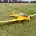
I've just completed building the Challenger kit now starting to cover it. I previously had the ARTF version for 3 years, was my go to model for a bit of fun, flying too low and fast hit the ground! Bought the kit at the start of lockdown for something to do. Don't bother with the wheel spats as has previously been said. I had an OS 55AX in mine no additional weight required for c of g, the build instructions say 46-2 stroke or 70-4 stroke. There is and good videos build on youtube (link below) which takes you through the build, the booklet that came with the kit has a few points missing or in the wrong sequence. If its your first kit build it would be worthwhile looking at the videos.1 point
-
I'm still waiting for my new number, but I guess there is no rush at the moment. I do wonder why the number is so long, after all the National Insurance number is only 9 digits and my NHS number is only 10 digits.......perhaps model flying is more popular than we thought!1 point
-
I've got a large box of balsa bits. I suppose I could start a new currency called Bitbalsa.1 point
-
Why though when Vanessa costs nothing, is easier and more accurate?1 point
-
Well I've made a start on producing the foam wing1 point
-
No, I did not. I am happy with the way it flies on a 1.5 mAh battery and 60 g extra ballast directly behind the motor. Edited By Max Z on 06/06/2017 15:10:261 point