Leaderboard

Popular Content
Showing content with the highest reputation on 16/07/23 in all areas
-
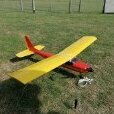
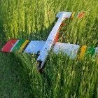
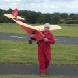
Well, it's winter in the southern hemisphere and we've had a really wet one so far. Mind you, that's better than the recent drought where we almost ran out of water. But with an almost summers day forecast, a mate and I took off this one day last week. Pinocchio hasn't been flown lately, so it got an outing. Lunch on the coals, as usual... Pinocchio x264.mp44 points
-
There comes a time when every fart is a gamble.4 points
-
I’ve managed some more time on the build again so I thought it was about time for another update. This time I’m covering pages 17 and 18 of the build guide – sheeting the tail fin, constructing the tailplane, elevators and rudder. I was working on various bits at the same time but will endeavour to list them below in some kind of logical order! Before sheeting the tailfin I had to build the internal frame thickness up in the central portion and then sand it to an aerofoil shape (allowing 1.6mm for the sheeting either side). Holding the balsa sheet in place whilst the glue dried to quite a bit of tape and pins. It was at this point I noticed what looks to be an anomaly within the plans. The fin and tailplane are designed to slot together and there is a 10mm slot in each for this purpose but the finished thickness of the fin and tailplane is in the region of 18mm – way too large to fit in the slots. I had yet to make the tailplane so could make a larger slot no problem but there wasn’t much material to play with on the fin. I ended up gluing some block balsa above the slot (which also served to support one of the Robart hinges) and then glued a thinner strip below, still leaving some space for my servo wires. At this time I also glued in some small pieces of ply to provide something a little more solid for my servo cover screws to tap into (the pencil dots marking their locations). I emailed the plan designer regarding the slots so maybe the plans will be revised at some point in the future. With the slot opened up in size I was then able to sheet the other side of the fin – yet more pins! As shown on the plans the tailplane looks to be of an open framework design to be covered with Solarfilm or the like. But I wished to sheet mine in the same way as the wings so revised the plan accordingly, introducing the wider slot along the way. I used a piece of basswood for the tailplanes trailing edge to give it a bit more strength and then balsa everywhere else. Whilst the tailplane is nominally flat the underside does rise up towards the tip more than the upperside comes down so it does end up with a small amount of dihedral as a result. I sheeted it top and bottom with 1.6mm balsa Sanded it back Added the leading edge pieces and sanded those to shape And then added the tips using the same ply sandwich method as for the wings and sanded those to shape too The rudder construction went pretty much according to plan but I again included a ply sandwich to help give a neater and sharper trailing edge. As with the fin the rudder needed to be sanded to shape allowing 1.6mm for the sheeting Prior to sheeting I made and glued in place a fibreglass control horn. I made a cardboard template for my servo cover Once happy with that I then made one in 1.5mm ply, hopefully once fully finished it should be reasonably discreet. The elevators are made in solid balsa and linked together with a tie bar. Again I wanted to make a fibreglass control horn but it took me quite some time to figure out a secure way of attaching it, eventually settling on two pieces of fibreglass slotted together and sandwiched within one of the balsa elevators. After some considerable sanding I eventually had something resembling an elevator With both sanded and the tie bar inserted it was starting to look like it might just work. The next task was sanding the leading edges and fitting the hinges. Thank you to the chap who spoke to me about my Sea Hawk build on the Orme the other weekend (apologies I didn’t get your name) but this time I endeavoured to keep the slots accommodating the Robart hinges to a minimum. In my naivety when making the ailerons I cut the slots full depth right down to the hinge points meaning it is very nearly possible to have +/- 90 degrees movement, great for flaps but far more than necessary for ailerons. With the tailplane and elevator assembly installed you can see that in time it will be necessary for some balsa infill pieces front and rear. I sanded and hinged the rudder in much the same way and then assembled that too Suitably pleased I thought it was time to add the wings again. I’m starting to feel like the end of the build stage will soon be in sight, just 4 more pages of the build guide left now (plus not forgetting the nose that I skipped on page 16). Items still to do are the ‘bullet’ which fits in front of the tailfin (no idea what function that performs), the exhausts (could be fiddly), canopy and cockpit. Then of course there will be the other detail stuff to think about like the arrester hook, no idea how I’m going to make that yet (unless anyone is able to 3d print one for me of course) but it will be attached by magnets. Phil3 points
-
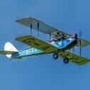
Oh I see. Well here are a few of mine. The Big Guff because it's the first model aircraft I'm aware of which was specifically built for radio control. The Junior 60 because I learned to fly on one. The Telemaster because I passed my A Certificate on one, actually the Telemaster 66 not the Senior Telemaster in the picture. The BE2e for its presence in the air and its overhead exhaust and the Acowot because it's a classic.3 points
-
No do it by hand. You have two sticks and two hands, and if you need to program a mix program the computer in your head and not the one in the radio. I say this as you will need to use rudder and aileron in opposition at times to keep the thing on an even keel and the radio will not allow this. Rudder coordination is a useful skill will be especially handy in any sort of a cross wind with any model. The rudder is sadly neglected by most model flyers and its something that always baffles me as i use my rudder almost as much as my ailerons and elevator. When it comes to c/g i was going to post something to the effect of 'balance it slightly nose down as the back edge of the top wing centre section' as that would be close enough. I then smirked to see the post above with the c/g in more or less that exact location.3 points
-
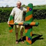
HA! amateur LOL🙂 this one was built by a club mate back in the early '90's and was the 'gifted' to me 🤨 ten years later................... almost finished !!3 points
-
Hi Toto, you're doing a grand job assembling this plane, however, there is one thing I would like to see and that's lock nuts on the clevises. GDB2 points
-
Anyone who doesn’t is a bit strange to my mind. Props don’t care what the energy source is.2 points
-
I live in a small country town in Australia and have had a standing order for RCM&E and other magazines for over thirty years. I often receive offers to 'subscribe' but to me what is that in reality? The vendors make a bit more profit but more importantly, my lovely and loyal local newsagent could be forced to close if enough people chose that option. My local newsagent employs four or five local people and even through covid they amazed me when not an issue was missed - when I queried this I was told that as a long term customer I had a high priority on the (limited) distribution list 🙃. I am proud that I am helping to keep a local small business viable and just like hobby shops (still have one locally) without support they fade away until they are just a memory. To reply to the above quote. - So just how would the publishers actually determine that I was not a long term buyer of the magazine? Regards * Chris * (A loyal customer and avid reader)2 points
-
Curare and Magic!2 points
-
Hi Fellow Rc Fliers....... I'm gonna set you all a Classic Photo Challenge to post/share what ever classic Planes or Helis you currently have, fly or any you are working on which I will go first and start with mine......... It's a Waterhouse & Eley Superfly (Electric) which I must say is my favourite plane of all the planes I have either had or flow in my flying life1 point
-
OK ..... the next victim on the slab is none other than the Phoenix Domino. and a peek in the box ...... My previous assembly the Arising Star is ... to all intent and purposes .... complete ..... bench checked / tested and awaiting a break in the weather for its maiden ...... so .... in order to keep you all rooted on the edge of your seats ....... My next assembly ..... the sequel ..... 😄 Very similar to the Arising Star in terms of general general construction but we are going EP with this model. I don't have the exact details of the power plant that will be going into this yet. I have some Spektrum Avian motor and ESC but think that it could be a bit over the top in terms of spec and price for what the domino is. So to be confirmed. probably running with the same servos as I went with in the Arising Star Savox SC - 0253 's. Again I know these are probably slight overkill for this model but will give me more options as to swapping them out into other models later on if I choose to. The receiver will be a Spektrum AR 620 ... again the same as the Arising Star. the receiver isolator switch will mimic the Arising Star as well with the dual switch / recharging point. Plastic clevises changed out for metal and I may take this opportunity to look at some of the servo linkages etc and change them out where necessary ( Z bend etc which I never used to like ...... I'm liking them now 😀 ). anyway, I'll feed more through as it becomes known and start the assembly at some point soon. I'm considering taking a well deserved break after a solid week with the Arising Star and letting rip on my Flight simulator for a bit. lets see how long I can resist the temptation to get into the box ......😀 Toto1 point
-
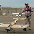
Most of us may have heard that distinct sound of control surface flutter, which usually ends in abrupt disaster This is a .60 Hobbico Trainer that I aquired as an engine test bed. It always had that flutter sound and I'd often shout out to the previous owner to "slow down". When I actually saw what flutter looks like, this model was immediately grounded for a complete rebuild. Aileron Flutter x264.mp41 point
-
How longs a piece of string, some new lads I have taught to the solo stage never go on to become more than average, others have progressed rapidly, some of it is inherent ability, most is self discipline and practice/practice/practice. A question that can only be answered by the individual.1 point
-
I think it takes flying to another level. I'm sure with practice ...... lots of it ...... you would get there but maybe not anytime soon. I dont think this level of attainment happens overnight. Whilst I understand its horses for courses, to be honest this kind of flying doesn't really interest me personally but I do like to watch others practice their craft, By the sounds of your previous posts Paul, you seem to pick things up very quickly ( inverted flying for instance ) so keep going and I'm sure you will get there. The best of luck with your endeavours. Some progress videos would be amazing. Toto1 point
-
OK .... here we are with the control surface horn connections / fitting ... here is what you get ...... notice the plastic clevises .... which actually look robust enough ...... but which I swapped out for metal anyway as I had some ..... and here we go ..... easy enough ..... in with all three and on with the metal clevises ... sizing up the first elevator control horn for drilling ... and bending in to shape ... with the bend .... and the second elevator .... job done ..... onto the rudder .... here is what I was not too keen on ...... the horn goes way past the hinge line where you would normally centre it over in order to get best geometrical movement either way .... but I need not have worried as I tried out the movement manually and it works out fine .... so happy the man ..... and inside the fuselage where it all comes together ..... SO ..... that it for now. I think I will look at giving the wings a test fit as I don't have the servos to continue with the Aileron push rod fitting. I think you need to have the servo to test fir the aileron push rods etc to ensure everything is in line. So ...... dramatic halt there and in the fuselage for now. \The servos should be here by around Tuesday I reckon. I should be back with a couple of piccies of the wing fitting test. cheers for mow toto1 point
-
Rather slow progress but the fuselage formers around the duct are on. It requires more and more thinking about how to do each step and then hand fitting to get the required final shape. It is no way to build a plane but the end result is, or should be, very light. Next is the nose/cockpit section. It will be build separately and glued on to the first former. Well that's the plan.1 point
-
In Paul's case the Gendarmerie (Sp?) are the one's are unlikely to take action. 😉1 point
-
As this is now so far off the OP, and I think that I've already answered his question, I'm out.1 point
-
There must be a blockage in the spraybar tube. The air that you get flowing just before the needle drops out must be going past the needle’s thread and O ring. If you remove the needle, and unclip the friction spring, you can use an 8mm socket to unscrew the tube that the needle goes in to. If you then look into the hole you will see the spraybar hole. This must be blocked with old fuel residue or something. Clean it out using methylated spirit or clean fuel and a piece of copper wire or similar. Under no circumstances use a steel wire or anything like that. A paintbrush bristle is also good. When the spraybar is clear, you should be able to blow into the hole, and with the throttle fully open and with a finger over the fuel inlet pipe, hear air hissing out of the carb. throat. Hopefully you will just about be able to see the spraybar hole in the photo below. That should clear the problem. Brian.1 point
-
Ok chaps, Am I correct in saying that one of the toggles on the transmitter could be set up as the kiil switch? Toto1 point
-
The biggest risk when retrieving an electric model after landing is if you knock the throttle up whilst collecting the model/disconnecting the battery. That's why you should always have a separate kill switch set up to disable the motor regardless of the throttle position. Land, throttle to lowest position engage kill switch, collect model/ disconnect battery. An extra layer of safety is a battery isolation plug in a place with easy access away from the prop but it is another connection with the potential to fail in flight.1 point
-
IMO. & to be totally honest comments like yours are not only meaningless,, but rather pointless too.. Using the word " Classic " in my thread title was done in the same way as if i used the words vintage or old1 point
-
IMO the word "classic" has become overworked & often inaccurate to the point of being virtually meaningless. Same applies to "awesome", "iconic" & a number of other superlatives.1 point
-
With some models I look on the screw fix (would be a good name for a company 😊) method as more of a maintenance aid & occasional long term storage. Any glue would be an unnecessary nuisance.1 point
-
Ah, that explains a lot but must come in handy for when flying off water and retrieving those Castor soaked crashed models 😂1 point
-
In my case a "classic" is one that has lasted longer than one flying season and to me taking a good photo is more than a challenge !1 point
-
Cough - splutter where is the defibrillator.1 point
-
What is a Classic Model Aeroplane and why is a photo of one a challenge?1 point
-
Other club members reported covering lifting issues with Seagulls Boomerang so I used a couple of coats of aerokote over the seams, no lifting yet. https://deluxematerials.co.uk/products/aerokote-gloss1 point
-
Hi Robin . No not the one. It was designed to fit into a tobacco tin , 4 oz tin I believe. If my memory is correct It had 2 or 4 push buttons on the front and battery was a PP3 9v . It was i think o er a couple of editions an had a section on making the PCB using Ferric Chloride thst you could easily buy from the local chemist. You could also buy Ether easily for making diesel fuel for oyr engines. Exciting times then as there was always a parts list and a local radio shop near Clapham Junction in Falcon Road where you could buy parts although pockey money in those days meant a long build time. Thanks for looking. E.D.1 point
-
Only if Trigger’s broom re-used the original nail to hold the head on. I did contemplate using the original Enya .09 which lurks in a drawer of old engines but decided on a more modern Leo .15 - although the MacGregor Codamac transmitter and receiver hiding in the attic were more easily dismissed.1 point
-
Is an O level the term for ground level as in a lift ?.1 point
-
Not something to take chances with. I witnessed a fairly large aerobatic model encounter flutter - it removed one aileron but landed safely but worse, the violence of it actually cracked the main spar! A controlled full size flutter test (and brave test pilot)1 point
-
Rebuild of the Sterling Cessna 180 which started my RC career in the mid 70s. When I say rebuild, I started with its original metal cowl piece and a downloaded plan from Openzone… 3 channel proportional switchable to simulated single channel replaced the original MacGregor Codamac single channel system.1 point
-
Model Fixings have M2 and M2.5 Nyloc nuts and a lot more stuff as well. A site worth looking round and a good company to deal with. https://www.modelfixings.co.uk/nuts.htm#metric nyloc nuts Dick1 point
-
Do you mean Oldest planes still flying ?, if so a couple here, Marutaka Spitfire Enya .90 4C, around 1993, Rafale ducted fan kit that I put a Wren 54 kit turbine in it in 2009.1 point
-
Weather was fine when we had the "Spring" thread but yous had to rush things, kids today eh.1 point
-
Couple of on the bench pictures of my latest pair of models, intended for single channel radio, once they have their maiden flights under three channel proportional under their belts. First one is a Ken Willard Schoolboy, built for this weekend's Pontefract fly in and single channel vintage event. LIkely that I won;t be flying the sChoolmaster, as I haven't managed to get a maiden flight in yet and it's pouring down here today. Powered by a tiny 1106 brushless outrunner, mounted on a dummy Cox Tee Dee .010 motor I was surprised quite how much waft the diddy motor and 2.5" prop generated. Model is built from the Outerzone plan and I opted for the original open strucutre wing, rather than the sheeted wing of the Tru-Flite version. Second one is a Keil Kraft Outlaw, builtfrom a short kit and plan - again from the Outerzone - I'm building this OUtlaw fifty years since my first unsuccessful attempts at radio control. AS she's only finished this morning, though intended for the Potefract event she won't be eligible to fly, but can have a ride in the car. 🙂 I'm building the Outlaw with two fuselages, one electric powered and one with a PAW diesel - either a 1.49 RC or a 19 RC - yet to be decided.1 point
-
I flew my Guidato on Wednesday but it was very marginally powered by the ASP 30FS and I couldn't get the engine to run reliably so yesterday I installed an OS 40 Surpass which involved using a rasp to remove some of the wood from the inner surfaces of the oak engine bearers to accomodate the OS's wider crankcase. I removed the lead from under the engine and temporarily fitted a fixed nose leg. There was no lack of power this this time and the OS, turning a 13x4, prop sounded very nice as it cruised around the sky. I will fit a steerable nose leg eventually but that will probably involve removing the battery, throttle servo and fuel tank mounting plate so I'll stay with the fixed undercarriage for the time being. The Guidato is a slightly bigger model than the Super 60 and a fair bit heavier. I regret that precise numbers are not available at the moment because my scales have broken. It has a shorter nose, shorter moment arm and slightly smaller tailplane too. Consequently it's a bit more resposive to control inputs compared with the Super 60 but it's pleasant to fly and just a matter of getting used to its flight characteristics. Overall I'm very pleased with it and it makes a change from all of those Junior 60s and Super 60s.1 point
-
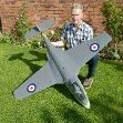
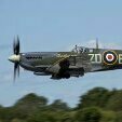
Three of us today in the Vale of York, breezy but bright and warm and managed to get the grass cut. Broke the mast again on my Gyroo after it went in. Both of us are having real difficulties with sustained flight. But that was all forgotten when 2 P51 Mustangs with invasion stripes in really close formation gave us a personal display. They circled the patch twice, performed a close formation loop followed by a victory role signing off with a wing waggle. Phone pictures don't show how close they were. THAT MADE OUR DAY 👍 Looked on the free Flight Radar and another but couldn't see any trace 😥 Anyone able to put up a track assuming they had transponders - around 3.30 give or take today. Just north of Tadcaster, w of York & e of Wetherby.1 point
-
Despite leaving my house for the strip in rain we were rewarded with fantastic weather this morning.1 point
-
While on the topic of making up servo lead extensions, I'm not sure how many forumites do that but for those who don't here's a short "how to". Many years ago, I took up making my own servo lead extensions. The advantage is that you can make the lead to exactly the length you want. Additionally, you can reduce the standard servo lead to the length you want which is what I did for the twin elevator servos on the Anthem. However, like everything in life, you must have the right tools! This photo shows what’s needed. Firstly, you need a wire stripper and the orange coloured set of pliers is just that. You need to strip about 3 mm of covering off the wires and this tool allows you to see how much you will strip and do all 3 servo wires simultaneously. Next you need a pair of needle nosed pliers. You need these to close the “wings” on the wire crimps that hold the wire and the insulation. Finally, you need a pair of good quality crimping pliers. You must buy the sort that is suitable for crimping servo wire and aim for an automatic action i.e. one that you can press home fully and that will then crimp to a set pressure and then release itself and spring open when you release the pressure on the handle. You must also buy the plastic plugs and crimps but those are readily available. You can get Futaba style plugs with the little flat that provides correct orientation or JR style plugs that don’t have these little flats. If you cut off the flats on Futaba style plugs you can use them on JR sockets and, of course, you can use JR plugs on Futaba sockets but the onus is on you to get the orientation correct. So, having got all these bits, this is what you do next. First, strip the wire using the stripper pliers. The photo shows that I’m making the plug with the male connector. Next, separate the 3 wires. I find making a small cut with a sharp modelling knife to start the separation process is very helpful if your nails aren’t particularly strong! Then twist the ends of the wires together to stop them spreading out. Then, work out which way up you need to have the 3 wires to attach the crimps. The signal wire, white here, must always be on the left with the crimp positioned as shown in the picture. This will keep the wires in the correct configuration and the bar across the crimp at mid section will be locked into the socket when inserted. The next task is to squeeze the 2 “wings” on the left of the crimp in the photo. This is the slightly fiddly bit! You need to hold the wire and crimp with one hand and use the needle nosed pliers (small non needle nose pliers are OK) to squeeze the “wings” together as in the next photo. If you don’t do this, the next part of the operation becomes decidedly iffy as the crimp falls off as you touch it with the crimping pliers! I learned that the hard way early on! Finally, apply the crimping pliers making sure that you don’t cover the bar across the crimp as that will destroy it! Close the pliers completely till you hear the click signifying that the correct amount of pressure has been applied and the crimping force has been released. Then allow the handles to open and remove the perfectly formed crimp! Well, it might take a few dummy runs to get it right but learning how to do this is a great help when you want to avoid a large amount of wire cluttering up a small space. Good luck!1 point